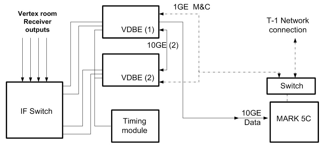
Fig 1: VLBA Digital Back End Block Diagram.

The VLBA, completed in 1993, is now undergoing a development project to increase the sensitivity of the instrument. Until now, the VLBA has been able to observe only at a total sustained bit rate of 128 Mbps (32 MHz with 2 bit samples) with a maximum bit rate of 512 Mbps for special projects. However, the analog IF electronics provide over 500 MHz in each polarization from most of the receivers. This is enough bandwidth to support 4096 Mbps recording. New technology now will enable the VLBA to routinely observe at 4096 Mbps, fully utilizing the two existing IF signals from each receiver. There will be a 4 IF capability for dual band observing, although still subject to a maximum of 4096 Mbps.
The upgrade project will:
The existing VLBA electronics that will be replaced in the upgrade are the IF Distributors, the Baseband Converters, the Samplers, and the Formatter. The existing Mark5A recording system will be upgraded to a Mark5C system.
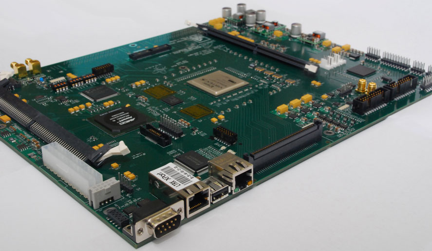
The upgraded system will include two VDBE (VLBA Digital Back End) modules, a timing module, and switches to route the signals in and out of the VDBE modules. The VDBE essentially re-implements the current VLBA backend system digitally. The heart of the VDBE is the ROACH (Reconfigurable Open Architecture Computing Hardware) board. The VLBA project will use two ROACH boards, along with dual 8-bit 1 G Sample/sec Analog to Digital Converter boards, to sample, filter, and format the data. The Mark5C uses large capacity commodity disk drives for recording. The input to the Mark5C from the ROACH is 10 G Bit Ethernet.
The ROACH board is the result of collaboration between NRAO, CASPER (Center for Astronomy Signal Processing and Electronics Research) at UC-Berkeley, and the South African KAT (Karoo Array Telescope) project group. The mission of the CASPER group is to provide easy to use, off-the-shelf hardware with development environments that enable non-experts to develop useful instruments. The South Africa group is using the ROACH as a major component of the MeerKAT project. CASPER provided the coordination of the development work on the ROACH and purchased the first ten boards. They are also porting their FPGA (Field Programmable Gate Array) development tools to the ROACH. The schematic design of the ROACH was done by the South Africa group, and the layout of the board was done by NRAO Socorro.
The ROACH utilizes the large bandwidth and high performance computing facilities of the Virtex 5 FPGA, the latest family of Xilinx FPGAs. The main components of the ROACH are the Virtex 5 FPGA, a Power PC CPU with associated memories, and I/O connectors.
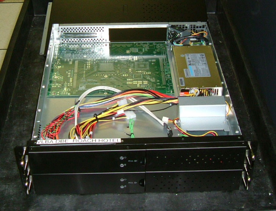
The ROACH is physically designed to fit into a standard ATX computer case and operate from standard supply voltages provided by PC power supplies. This minimizes the amount of work necessary to get one of the instruments running.
The Virtex 5 on the ROACH has a large amount of logic and signal processing hardware available. The chip selected for the ROACH has 640 18 x 18 bit hardware multipliers with associated accumulators, as well as 80,000 logic elements. Each logic element consists of a 6-bit lookup table that can implement any arbitrary Boolean function of 6 inputs with an associated storage element. This element can be configured as a flip-flop or latch. A significant number of 4 K bit block memories are available. This chip is suitable for processing the 8-bit samples that arrive at the ROACH board at the rate of 1024 M Samples/sec.
Haystack Observatory is providing a significant software contribution. Functions are implemented within the FPGA to process the very large amount of data entering the ROACH board from the Analog to Digital Converter Board. A polyphase subband filter bank splits the input bandwidth into four 128 MHz subbands, as the FPGA will be clocked internally at 256 MHz. There will be digital Local Oscillators and mixers as well as digital baseband filters to implement the functions that replace the VLBA baseband converters. Digital Re-quantizers will re-sample the filter outputs to 2-bits for recording, formatting, and packetizing logic. Ethernet packets will be built in order to send the data to the Mark5C recording system. Pulsecal tone detectors and switched power meters will also be implemented in the FPGA to collect monitor and diagnostic data. There will be polyphase modes for continuum observations, and digital down converter modes with flexible tuning for spectral line observations.
A major advantage of the ROACH board is that upgrades can be made without a change to the hardware. As requirements evolve, the ROACH functionality can be changed by re-programming the ROACH.