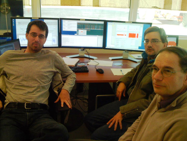
Figure 1: The Dynamic Fringe team ponders success: (left to right) Jeff Kern, Lewis Knee, Robert Lucas.
Figure 1: The Dynamic Fringe team ponders success: (left to right) Jeff Kern, Lewis Knee, Robert Lucas.
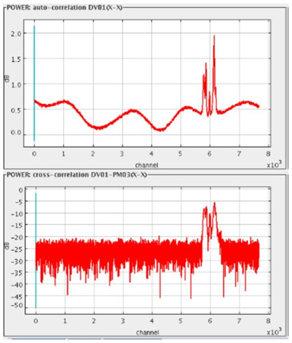
Figure 2: Upper panel: The spectrum of the 86 GHz SiO maser toward Orion, as observed by ALMA Vertex antenna AIV1. Lower panel: The interferometer spectrum on the baseline to the Melco antenna.
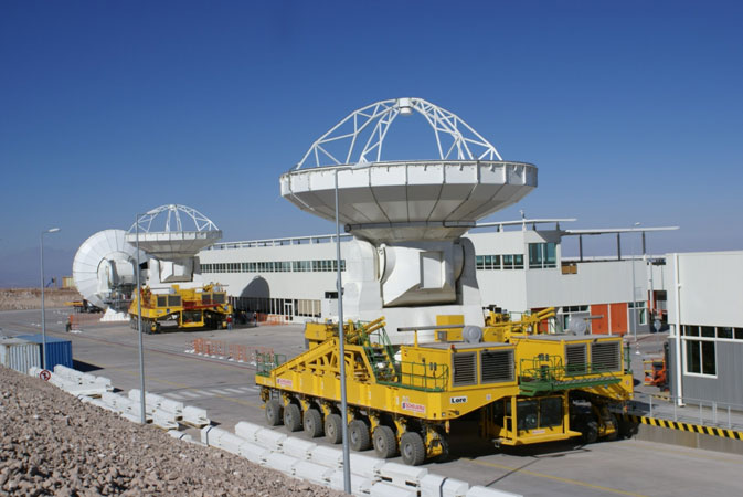
Figure 3: Vertex antennas No. 4 and No. 2 were moved to new foundations at the Operations Support Facility as testing continued. Photo: Luis Roa.
The first two ALMA antennas were pointed at an astronomical source, Mars, on April 30 and ‘static’ fringes were observed, i.e., software did not control or follow the changes in the fringes as the source followed its diurnal path. Updated ALMA software (v6.1) has now been installed, and on June 12 ‘dynamic’ fringes were obtained, for which computations are continually updated to drive the electronics and track the changes in the fringes as the source treks across the sky. The spectral lines from the silicon monoxide (SiO) maser in the heart of the Orion Molecular Cloud were observed at 86 GHz by a team that included Jeff Kern, Robert Lucas, and Lewis Knee.
The ‘single antenna’ spectrum from the Vertex antenna, and the spectrum on the 69.7m baseline between the two antennas are shown in the upper and lower panels, respectively, in Figure 2. The baseline variations seen in the upper spectrum will be removed by calibration, not applied in these test spectra. The two spectra differ because of the lack of calibration and becuase of intrinsic source structure. The interferometer is more sensitive to small-scale structure, and measuring these differences on many scales (baselines) leads to a high-resolution image of the source. In this case, the primary beamwidth of the 12m antenna is 72 arcsec, and the scales to which the interferometer is sensitive include those shorter than the baseline measured in wavelengths (3.5mm), or ~ 8 arcsec.
Meanwhile, the surface of the Vertex antenna accepted in April was set to well within specifications. This antenna has also undergone rigorous pointing tests and been equipped with an ALMA Front End received from the European Front End Integration Center at Rutherford Appleton Labs, a Back End from the NRAO Science Operations Center in Socorro, and other equipment. Radiometric measurements will be conducted soon.
ALMA equipment continues to be delivered to northern Chile. Vertex antenna No. 10 arrived in May and will be erected over the coming months. Figure 3 shows the exchange of two antennas at the Operations Support Facility using the two ALMA Transporters. Each loaded vehicle weighs about one‐third million pounds. Water Vapor Radiometers are also arriving, and the fourth has now gone through acceptance. The second Test Correlator, the device used at the ALMA Test Facility in New Mexico, will arrive soon.
At the high elevation Array Operations Site, the antenna foundation nearest to the Technical Building is receiving its electrical power and optical fiber connections in preparation for the arrival of the first antenna.