Photo by JMarkStrong.com
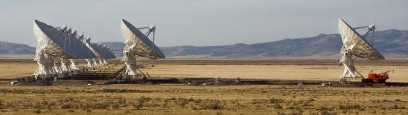
Antennas continue to be retrofitted to the EVLA design at the rate of six antennas per year. A total of 15 antennas are now used in scientific observations and account for 52.9% of all antenna hours used in observations. The electronics outfitting of the 16th antenna is underway, and the mechanical overhaul of the 17th antenna has begun.
Preparations are underway for the arrival and initial testing of the first parts of the WIDAR correlator. A 4-station prototype correlator (PTC) will be installed in June, and prototype tests will be conducted through September 2008. The racks and cables for the full correlator will be installed in May through September. Limited observing with a 10-station correlator will commence in October. Access, cleanliness, and electrostatic discharge procedures will be implemented in the correlator shielded room in early October. The humidity control features of the HVAC units in the correlator shielded room were placed in operation in March 2008.
In Penticton, British Columbia, extensive tests of the "stage 2" prototypes for the correlator’s station and baseline board have been conducted. The station board provides delay tracking and digital filtering for the correlator. The baseline board contains the correlator chips where the correlations are computed. The final design of the station board was approved, and the "stage 3" build of 14 station boards was completed. Testing of the baseline board is still underway and has gone very well. The board is functioning as designed. However, some bugs have been encountered in the baseline board, and this has delayed the approval of the design for its next stage build. The delay with the baseline boards does not delay critical on-the-sky tests with the PTC in June, as the existing stage 2 baseline boards can be used.
The correlator chip manufacturer, iSine, delivered the production order of 12,000 chips to Penticton by mid-April 2008. The qualification testing of a subset of these chips was completed by MuAnalysis, a company that specializes in industry-standard qualification, failure analysis, and screen testing of integrated circuits.
Work has progressed on the monitor and control software needed for PTC tests in June. A document describing the software needed for both the PTC and the 10-station early WIDAR was started. A startup sequencer and a related graphical user interface for setting it up were created for the WIDAR baseline boards. The design and implementation of the Test Builder and Test Executor were started. This software will be necessary to set up the PTC for testing. An agreement between ALMA and EVLA on the binary data format (BDF) has been written. Existing code will be modified to write this version of the BDF. The writing of the minimal version of the Science Data Model (SDM) that will be needed for PTC testing has progressed to the point where real SDMs are being written to disk given current input on what the VLA is doing.
The EVLA antennas currently in the array use the EVLA’s narrowband (1 GHz) signal path. The full capability of the EVLA’s wideband (2 GHz) signal path cannot be exploited until the arrival of the WIDAR correlator. The first T304 baseband converter modules to be fully configured with wideband electronics are now being produced. The parts needed for the wideband path, such as the gain-slope equalizers and wideband filters, have been received and are now being included in the regular production build. The wideband upgrade of existing T304 modules will commence this summer.
Some LO/IF modules have not met phase stability requirements because of thermal effects in the modules. The phase stability of these modules is being improved by adding thermal mass and by replacing existing module cables with cables that are less sensitive to temperature variations. Investigations into module phase stability will continue in an attempt to identify any other problems, particularly in the course of testing the wideband signal path with the new correlator.
Work continues on studying the unexplained relationship between the phase of the antenna signal and antenna elevation. A more suitable signal injection technique was implemented to produce faster and more repeatable results during antenna testing. Laboratory tests were completed on modules in the data transmission system to eliminate the digitizers as a potential cause. Another test was run to exonerate the system software and VLA correlator. These tests confirmed that the issue is indeed in the antenna portion of the LO/IF electronics system. Tests are currently concentrating on the thermal behavior of the LO comb generator (a commercial product) and a circuit board in the downconverters.
The prototype Ka-band (26-40 GHz) receiver was shown to meet project specifications and was installed in antenna 4 on May 22. Fringes were recorded with this receiver by tuning it and the Q-band (40-50 GHz) receivers in the other antennas in the array to a frequency of 40 GHz. The installation of this prototype receiver was delayed due to unexpected conversion loss in its downconverter. The mass production of the Ka-band receiver will commence in Q3 2008.
Although the prototype C-band (4-8 GHz) orthomode transducer (OMT) met project specifications, its assembly and adjustment proved to be too time consuming. The mechanical design of the OMT was refined to simplify its assembly. Now, no adjustments are required after assembly for the device to meet its performance specifications.
The C-band OMT is combined with a 90-degree hybrid coupler to convert linear polarization into circular. This technique requires the cables between the OMT and hybrid to be phase-matched. Staff in the front end group were recently successful in accomplishing the phase-matching task. They also selected a hybrid that functions reliably at cryogenic temperatures.
In February 2008, production orders were placed for the S-band (2-4 GHz) feed horn’s centrifugal castings and fiberglass lamination. The production lamination of the S-band horns started in April. The horns will be assembled at the rate of two every seven weeks. The fabrication of the aluminum rings for the S-band horns continues at the VLA site.
Recent work on software for the EVLA’s Science Support Systems (SSS) has focused on the Observation Preparation Tool (OPT). An expert-user interface for manipulating the EVLA antenna electronics was made available within the OPT. Users who do not wish to deal with the instrument at such a detailed level will be shielded from this part of the application. Expert users, though, will be able to tune each local oscillator independently and will eventually have access to all hardware switches. The OPT was augmented in two other areas. The first augmentation was the creation of a summary tab for scheduling blocks that shows a listing of the scans in that block. To support this tab, an underlying model that includes the EVLA telescope motion model and celestial coordinate conversions had to be updated. The second augmentation was the addition of software that converts the project model into a script of commands (in the jython scripting language) that can be understood by the current observation executor. This ability is in the prototype stage and can currently handle only the simplest of observations.
Work has progressed on adding a model and user interface for the VLA correlator to the SSS software to support Ka-band observing on the VLA. The user interface will be similar to the one in the Proposal Submission Tool (PST). Scientists reviewed the interface, and their suggestions are being implemented in an updated version.
As recommended by the EVLA Advisory Committee and the AUI Visiting Committee, an integrated schedule was developed to illustrate how the EVLA construction project transitions to operations. The schedule shows how the required software and hardware come together in preparation for the first shared risk science observations with the new telescope. The schedule was used to develop an EVLA capabilities forecast.
M. M. McKinnon and the EVLA Project Team