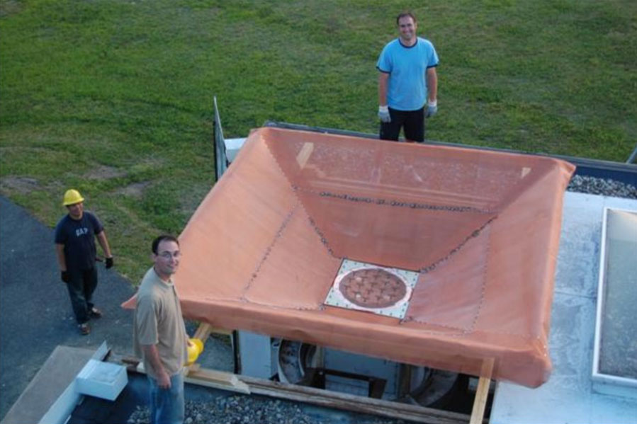
Figure 1: The phased array receiver and ground screen mounted in the Green Bank Indoor/Outdoor test facility. Clockwise from top are BYU students Jacob Waldron, Jonathan Landon, and Jiyoung Son.

Development work on phased array feeds shifted into high gear a couple of years ago, most notably in Australia, the Netherlands, Canada, and the United States. Phased array feeds (PAFs) promise to make much greater use of the information falling on the focal plane of a radio telescope than occurs with horn feeds or arrays. However, the close-packed nature of PAFs presents some serious challenges to antenna and receiver designers, mainly due to mutual coupling between array elements and the open-field electromagnetic configuration. NRAO involvement in this work is a close collaboration with Drs. Brian Jeffs and Karl Warnick and their students at Brigham Young University (BYU). Our group is concentrating on the RFI cancellation, low-noise matching, and cryogenic aspects of PAFs while other groups are leading wideband array research.
A PAF workshop in Holland sponsored by ASTRON in November 2007 was a milestone in international collaboration that resulted in a new understanding of mutual coupling and has led to a common definition of efficiencies that work for mutually coupled arrays. The most difficult questions were how to define the receiver noise temperature for a beam formed by a PAF and how to impedance-match amplifiers to the array to minimize noise. Karl Warnick was a major contributor to the workshop.
Figure 1: The phased array receiver and ground screen mounted in the Green Bank Indoor/Outdoor test facility. Clockwise from top are BYU students Jacob Waldron, Jonathan Landon, and Jiyoung Son.
In the January 2008 NRAO Newsletter we reported first beam-forming and interference mitigation results from the BYU/NRAO 19-element, 20-cm wavelength array installed on the Green Bank 20-meter antenna. In June 2008, BYU engineering students Jonathan Landon, Jacob Waldron, and Jiyoung Son worked hard at revitalizing the array receiver. They installed new, 30 K noise temperature first amplifiers to replace the old 100 K units. Their first objective was to understand the receiver noise before it went on the telescope. Measurements at the coaxial LNA input ports were relatively straightforward, but array measurements needed to include the dipole elements and reverse amplifier noise coupled to other array elements. This called for a “sky noise” Y-factor measurement, using the sky as a cold load and a large ambient absorber as a hot load. To suppress weak but significant pickup of ground radiation from array back and side lobes, a ground screen was necessary. The BYU team, with some help from Green Bank staff, built a large inverted pyramidal frame covered with copper screen to fit around the array. Figure 1 shows the ground screen and array receiver just before the first night’s noise measurements.
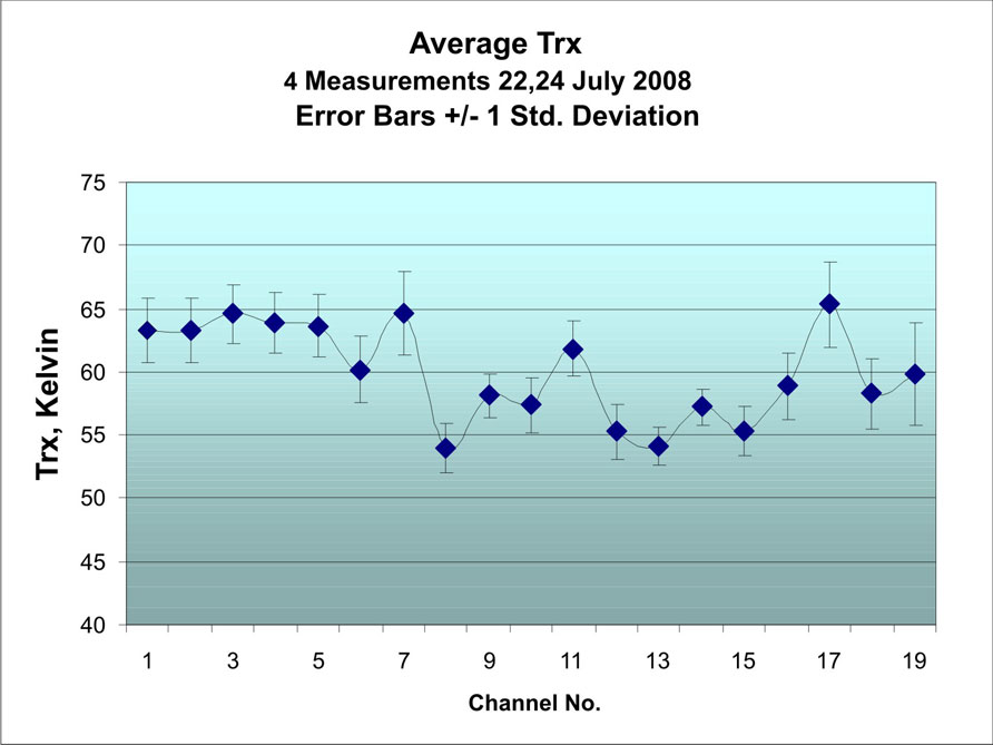
Figure 2: Receiver sky noise test results at 1612 MHz. Channel 1 is the array center element, channels 2-7 are the first ring, and channels 8-19 are the second ring of dipole elements.
Jonathan returned to Green Bank in July 2008 with fellow student Mike Elmer. Together with Roger Norrod and Bob Simon, they spent a week doing more array sky noise measurements before mounting the system on the 20-meter. Figure 2 shows the average results from four sky noise tests. Note that the center elements show higher noise relative to the outer elements, as expected due to mutual coupling between elements. The noise distribution in the array receiver on the telescope is roughly: 33 K LNA, 16 K mutual coupling, 7 K spillover, 7 K sky, 5 K ohmic loss. These values agree well with those predicted from known dipole impedances, coupling coefficients, and measured amplifier noise and impedance parameters. More importantly, we see how to improve on the mutual coupling noise with better impedance match of the dipoles to the amplifiers.
The proof in the pudding, of course, is to show that the array can make accurate, low-noise maps of the sky on the telescope and do so in the presence of interference. As the receiver went on the 20-meter, Brian and Karl arrived for eight days of observing. Using new telescope control software tailored to array tasks, the group calibrated the array by observing a strong radio source in a grid of positions in the field of view and computing beam-forming coefficients that optimized the source to system noise ratio at each point. The ratios agreed very well with sky noise measurements from the previous week and showed that the aperture efficiency of the array-telescope combination was ~ 70%, considerably better than is typically achieved with a prime focus horn feed. As far as we know, this is the best system noise to aperture efficiency ratio obtained with a PAF.
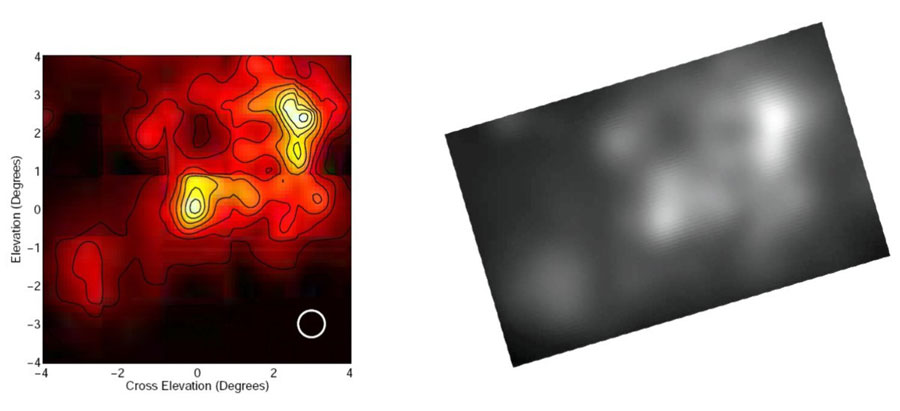
Figure 3. (left) A mosaic of maps of the Cygnus X region made with the PAF on the 20-meter telescope. Compare this to a composite map (right) of the same region from the Canadian Galactic Plane Survey smoothed to the resolution of the 20-meter (white circle on left image).
After the array was calibrated it was used to map the complex radio continuum field in the outer part of our own Galaxy, the Cygnus X region. Figure 3 shows a mosaic of array feed field maps compared with a 1420-MHz continuum composite map of the same region of sky from the Canadian Galactic Plane Survey, smoothed to the 20-meter telescope resolution. The 20-meter map would have taken 25 times as long to make with a single beam with the same system temperature.
In addition to forming multiple beams, the PAF can excise RFI by spatial filtering of the received signal. Additional 20m maps were made in the presence of strong RFI and results will be reported in a future eNews.
Understanding the noise, efficiency, calibration, and RFI mitigation properties of an uncooled array is a key step toward a PAF whose individual beams have noise temperatures similar to the best single-beam receivers. This is our ultimate goal, which requires that we do the engineering research that would allow us to cool the amplifiers and probably the array elements to cryogenic temperatures. Many of the techniques used in conventional cooled receivers, such as massive coldstraps and conventional vacuum windows, will not work in open-structure arrays. There are interesting challenges ahead.
Acknowledgments
The BYU Radio Astronomy Laboratory research into phased array feeds is partially supported by ATI and MRI grants from the National Science Foundation.
For assistance with this summer’s experiments, thanks go to the Green Bank Electronics, Telescope Operations, and Plant Maintenance staffs. Special thanks to Pete Chestnut, Bob Goldizen, and Rusty Taylor for cheerful assistance after equipment failures, even though, as usual, the problems happened at inconvenient times.