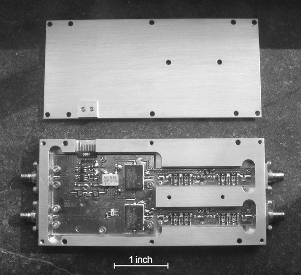
Figure 1: The L-band sideband-separating mixer. The housing measures 4.25 x 2.0 x 0.5 in.

The next generation of radio telescopes will need many more receivers than are used on current instruments, either to increase the field of view with focal-plane arrays of feeds or to increase collecting area with many more antennas. This requires that new receiver systems must be less expensive, smaller, and lighter, and consume less power without sacrificing the noise performance of the best current receivers.
The core function of a radio astronomy receiver intended for spectroscopy is to convert the very high frequency astronomical signal to a low frequency where it can be sampled and processed in a digital signal processor, such as a correlator. This has typically involved several frequency conversion (mixer) and filter stages to suppress receiver responses at unwanted frequencies. Each mixer has two responses: upper and lower sideband. The filters suppress the unwanted sideband that would otherwise overlap and be confused with the desired sideband.
The idea of using just one conversion stage and canceling the unwanted sideband with analog phase shifters, usually quadrature hybrids, has been around for a long time. Sideband-separating SIS mixers are used extensively in ALMA receivers where 10 dB sideband rejection is sufficient to minimize receiver noise. The stumbling block for use at lower frequencies has been that analog phase shifters cannot be made accurate or stable enough for adequate cancellation of radio frequency interference (RFI) from the unwanted sideband. The advent of small, high-speed digital signal processing devices gives new life to this old idea. Digital phase shifters are rock stable and can be easily calibrated to compensate for errors in the few necessary analog components.
To test the achievable performance of a single downconversion, sideband-separating receiver using digital signal recombination, we built a system tunable from 5 to 9 GHz with inexpensive components and numerous connectors and cables. The intermediate-frequency (IF) bandwidth was limited to ±27 MHz by the sampling rate of the available 14-bit digitizer.
The prototype receiver achieved sideband-suppression in excess of 50 dB over that entire range; a typical all-analog equivalent circuit produces 15 to 25 dB of sideband rejection depending on tuning range. No special amplitude or phase matching was required in the analog hardware. It only needs to be stable. Digital phase-shifter coefficients were determined for local oscillator (LO) settings over the full 5-9 GHz range, and we found that the calibration vectors can be factored to avoid the need for the full two-dimensional (IF and LO) measurement matrix. Quantization errors were shown not to degrade sensitivity or sideband suppression as long as the rms noise voltage is at least 5 analog-to-digital sample levels.
A follow-up version was constructed (Figure 1) using a more integrated approach to better evaluate the calibration stability over longer time periods, to test its performance in a demanding RFI environment, and to demonstrate the technique over a wider IF bandwidth using faster dual digitizers. It was designed for the Green Bank Telescope (GBT) L-band receiver (1200-1700 MHz) using a single fixed LO at 1450 MHz and 250 MHz bandwidth in each sideband. Both sidebands are available simultaneously.
The new mixer uses physical channelization of component layout to avoid coupling between stages and a new filter designed for better impedance match at all frequencies. Commercial surface-mount components are used throughout. The minimum size of the box containing the components is close to being limited by the size of the mounting flanges of the SMA connectors.
The results from tests of the latest mixer are excellent. Sideband separation is at least 60 dB over the entire 500 MHz band, and this degrades to no worse than 50 dB when the temperature of the box is raised 12°C above the calibration temperature. This is a much bigger change than is expected in practice. The next step is to attach the mixer to the output of the GBT L-band receiver to see how it fares in the real world of RFI.
The next R&D stage in the lab is to incorporate the A/D converters into the mixer chassis to assure that the switching noise from the digital circuits can be adequately shielded from the analog components. Then an optical fiber transmitter will be added to complete the goal of a small receiver package with an RF input connector and an optical fiber output connector that carries digital samples that can produce two well separated sidebands.
For more details on the digital processing mathematics and a description of the first prototype see NRAO Electronics Division Internal Report #320.
Figure 2: Spectra of two sidebands above and below the LO frequency of 1450 MHz with a strong test signal at 1600 MHz showing that this signal is completely suppressed in the opposite sideband.