Al Wootten
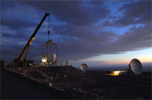
Figure 1: Major elements of the first of the ALMA antennas from the AEM consortium have arrived at the contractor's site at the ALMA Operations Support Facility (OSF) in Chile. AEM is a European consortium consisting of Thales-Alenia Space, European Industrial Engineering, and MT Mechatronics producing antennas under a contract with ESO. To the right are two antennas from Mitsubishi Electric Co awaiting further testing. Photo courtesy ALMA (ESO/NAOJ/NRAO)
 Zoom
Zoom
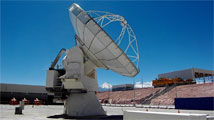
Figure 2: Now outfitted, a Vertex antenna undergoes tests at the OSF Technical Building. An antenna transporter can be seen near its shelter in the background. Further in the distance, the Licancabur Volcano stands sentry. Photo courtesy Denis Barkats.
Zoom
Two Antennas Working Together
Major components of the AEM antenna, contracted by ESO, have arrived at that contractor's area at the ALMA Operations Support Facility (OSF) in northern Chile. The receiver cabin and backup support structures (BUSS) have arrived. These parts of the antenna feature carbon fiber construction, while the other antenna designs have steel receiver cabins. The AEM panels and the antenna's steel base are expected to arrive soon. The cabin and BUSS elements of a second antenna have been shipped and are en route to Chile.
There are now 14 antennas at the OSF. A second Vertex antenna is scheduled for handover to ALMA in late April; this will bring the contingent of accepted antennas to three. The equipment needed to outfit the antennas has also been arriving at the OSF. The first of the sensitive receiver systems that have been assembled and tested at the European Front-End Integration Centre (FEIC, located at Rutherford Appleton Laboratories near Oxford, England) have arrived at the OSF as well, where they have passed their first tests. They have been joined by the first water vapor radiometer, also undergoing testing.
The first two antennas have passed their initial ALMA testing, which includes pointing and holography sessions. Contractor tests adjust the antenna surfaces using a transmitter on a tower mounted at a low elevation. ALMA personnel re-measure, then adjust the surface for an elevation more appropriate for astronomical sources, followed by more holographic measurements. Both accepted antennas show excellent performance—calculations suggest that for astronomy under most conditions, the surface accuracy should be well below the targeted 25 microns.
Installed within each of the receiver systems on these telescopes are four cartridges, covering 84-116 GHz (Band 3), 211-275 GHz (Band 6), 275-373 GHz (Band 7) and 602-720 GHz (Band 9). These systems have been tuned to spectral lines within the bands and a total power spectrum and small map of the 86 GHz SiO maser line has been obtained. Recently, the two antennas have been used to demonstrate interferometry using the 104 GHz transmitter located on the No 2 holography tower.
Infrastructure construction continues at the ALMA Array Operations Site, with 85 foundations now having received concrete. Electrical, fiber, and road connections to these foundations will be laid over the coming months.

