
|
Slide 1 is the cover of the report to the Navy in July, 1950. I scanned the slides in this ppt from my copy of the original report. I gave my copy of the report to Bill Shipley in 2003. Bill is a good friend in the field of radiation oncology at the Mass. General Hospital in Boston. His department operates 6 linear accelerators and one cyclotron.
|
| |
|
Slide 2: the Preface to the report and list of the authors.
|
| |

|
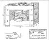
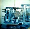
Slide 3 is a photo of the external beam machine installed in the Cyclotron, which consists of a beam scatterer, and the magnetic channel that accepts the scattered particles and directs them out of the cyclotron. The scatterer is shown later in greater detail. The magnetic channel was made in four sections coupled together to provide a continuous path from the entrance to the exit. Each section was remotely controlled to allow position adjustments while the cyclotron was in operation. This tuning capability was further enhanced by locating a Lucite rod at the end of each channel to intercept the beam. The resulting scintillations were measured by a scintillation counter integrated with rod such that they could be introduced or removed while the cyclotron was in operation. In this manner, each of the four sections of the magnetic channel could be adjusted separate of the others. The position of the scatterer could also be adjusted while the cyclotron was in operation. The appropriate order in which to make the several adjustments was itself a challenge. The magnetic channel was designed to shunt the field of the cyclotron by guiding it through the walls of the channel, outside of the central path of the particles.
|
| |

|
Slide 4 provides a brief summary of my two projects in 1950 and my approach to completing both of them. The external cyclotron beam was obtained on February 16, 1951 and the Hydrogen Line the following month on March 25th (Easter Sunday).
|
| |

|
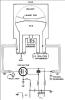
Slide 5 is a simplified view of the Dee structure with its tuning stubs. This is the basic tank circuit of the oscillator. The Dee structure covers one half of the space between the poles of the magnet. The particles are pulled into the Dee on one side and kicked out on the other by the electric field which oscillates in synchronism with their motion. The tank circuit includes two tuning stubs and a rotating capacitor between the two. The function of the rotating capacitor is to change the oscillator frequency in synchronism with the rotation frequency of the particles as they spiral outward from the center of the structure.
|
| |
|
Slide 6: this sketch captures the enormous nature of the magnet structure measured in tons.
|
| |

|
Slides 7-10 are a copy of a four page letter that I sent to Al Pote in December, 1947, suggesting a solution to the rotating condenser problem. The design at that time located the rotating plate well into the magnetic field. As a result, the eddy currents generated in the conducting material created very high temperatures in a region where it was difficult to dissipate the heat energy build up within the rotating material. My thought as described in the letter, was to move the rotating member out of the field by adding a piece of coax to act as a transformer (a trick I learned in the Navy). You can tell from the detail presented in the letter that I was hoping to be assigned to implement this task. Norm Ramey had other thoughts and I was assigned to get the beam out. The idea about the solution to the oscillator problem was accepted, but the task was assigned to another graduate student. He did a great job and the technique worked well.
|
| |
|
Slides 11-16 provide additional detail on the FM oscillator circuit and the location and function of the rotating condenser. Note in Slide 15 how the rotating member engages the stator, which is mounted on an extension of the coaxial member that functions as a transformer.
|
| |
|
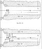
Slide 17: this sketch shows the conceptual approach to the magnetic shunt, which consists of two vertical members located on either side of the exit channel. These two members with the aid of the shims shown in the sketch, shunt the field causing it to pass through the vertical members introduced for that purpose. The scatterer that intercepts the beam and deflects it into the entrance to the channel is not shown in this sketch.
|
| |
|
Slides 18-24 are photos originally taken in 3D by the Physics Dept. photographer. They show the details associated with the motor drives that provided individual remote control of each of the four sections of the channel. Getting all of this hardware into the cyclotron took about one week with two three man shifts.
|
| |
|
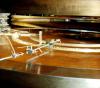
Slide 25: this photo is among my favorites: it shows the scatterer. The heart of the system is a railroad track carrying a very special car. An aluminum rod passes through the car. Each end is equipped with spring fingers. Those in the foreground engage the pole of the magnet. Those in the background engage a curved aluminum plate supported on a curved plastic plate, to electrically isolate the aluminum plate from the pole of the magnet. A battery and potentiometer provided a controlled current to be passed through the rod. With the field on, the direction of current flow in the rod causes the railroad car to move in either direction. The location of the car on the track was measured by introducing a string of resistors in series along the track. The junction between resistors was mechanically sensed by a wiper. The position of the car was determined by an ohmmeter circuit. The actual particle scatterer is the vertical rectangular piece of aluminum mounted on the circular drive mechanism located near the end of aluminum rod in the foreground. The outward radial position of the scatterer is adjustable by rotating its off-center mount about a vertical axis. Rotation of the off-center mount is accomplished with the aid of a solenoid driven pin which engages the ratchet controlled shaft of the off-center mount. This adjustment is made with the cyclotron field off, but with the vacuum intact. This gadget is one of my favorites because a visitor to the Cyclotron Lab asked me one day to describe my approach to the external beam. He was particularly interested in the scatterer. When I described the approach, he was most interested in the track and the railroad car. I mentioned that I had purchased them for a few dollars. He asked for further details. I told him that non magnetic brass cars and tracks are readily available at most hobby shops. He thought that was very innovative. He told me that they used the same railroad car technique, but all the parts were made at considerable expense and time in their own machine shop. He then told me that he was from Chicago and that most people called him Professor Fermi, but he would prefer that I call him Enrico.
There were two other visitors to Lyman Lab, that generated memories. One day a tall fellow dashed into the lab searching for a quick answer to a critical question. I immediately recognized that it was Bob Oppenheimer. He wanted to know how to get to Fenway Park to enjoy an afternoon Red Sox game. Then there was the time that a tall lanky fellow showed up at the front desk of Lyman asking for Doc Ewen. He didn't have to mention his name. Everyone knew it was Ted Williams. He had come by to say hello to his "former Prof from Amherst College." Ted and a few other ball players were students of mine in the Navy V-5 program at Amherst in '42-'43.
|
| |
|
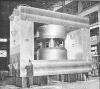
Slides 26-33 include detailed photos of the construction of the large parts of the Cyclotron. In many cases a metal frame was constructed and the concrete was poured in place.
|
| |
|
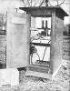
Slide 34: radiation monitors were a critical part of the operation. Monitor stations surrounded the Lab. They were particularly impressive in the Lab. Everyone wore a photo film monitor to measure the integrated dosage during the week. There were sensors located in the hallways that detected any over limit material moving in and out of the Lab. They were very sensitive. I was unable to wear my Naval Aviator watch, which I had worn for a half decade, because the illuminated dial tripped the over limit alarm.
|
| |

|
Slides 35-36 are exterior views of the Lab during the fall and early winter.
|
| |

![[Doc Ewen looks into the horn antenna, 1950]](ewen_horn1s.jpg)
![[Doc Ewen and horn antenna, 2001]](ewen_horn2s.jpg)