NRAO eNews
January 2009 • Vol. 2, Iss. 1
- Upcoming Events
- ALMA Progress
- Call for Proposals for NRAO Telescopes
- Nominations Invited for the 2009 Jansky Lectureship
 Lab Notebook: A Digital Back End for the VLBA Sensitivity Upgrade Project
- Spectrum Use after the U.S. DTV Transition
- Career Opportunities
- Past Issues
- Contact the Editor
- Subscribe
- More Information
NRAO eNews: January 2009 • Volume 2, Issue 1
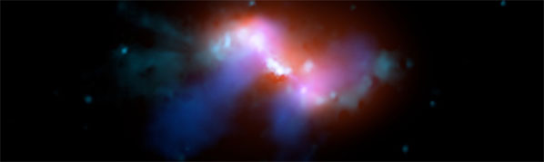
The second prize winner from the 2008 AUI/NRAO Image Contest. Francesco Massaro of the Harvard-Smithsonian Center for Astrophysics used radio, optical, and X-ray data to produce this compelling image of the radio galaxy 3C 305 in the constellation Draco.
Upcoming Events
 NRAO Summer Student Research Assistantships
Application Deadline is January 26, 2009
 NRAO Proposal Deadline (GBT, VLA, VLBA)
February 2, 2009 | 5:00 p.m. ET
 20th International Symposium on Space THz Technology
April 20-22, 2009
Charlottesville, VA
 Millimeter and Submillimeter Astronomy at High Angular Resolution
June 8-12, 2009
Academia Sinica, Taipei, Taiwan
ALMA Progress
Al Wootten
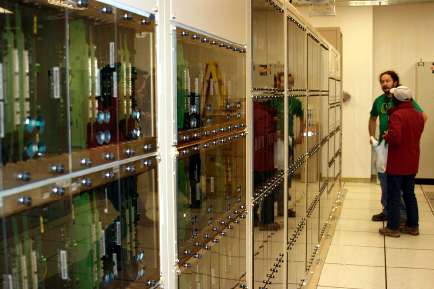
Figure 1: Alajandro Saez demonstrated the ALMA Correlator's first quadrant to the Annual ALMA External Review (AAER) committee.
With the acceptance of ALMA production antennas in Chile now underway, further system verification tests will occur on the full production system, initially at the Operations Support Facility (OSF) and then at the 16,570 foot elevation Array Operations Site (AOS). The first quadrant of the ALMA correlator is now operating in the AOS Technical Building.
The AOS site has been extensively reworked. Roads are being built to numerous antenna locations and dozens of foundations have received concrete. Hundreds of workers, contractors, and ALMA employees are making steady and significant progress on everything from heavy construction to the tuning and testing of the array’s cutting-edge electronics.
Antenna production lines continue their steady shipments to Chile. Thirteen ALMA antennas are now on-site and more will arrive in the near future. Both massive transporters traverse the site and have moved several antennas as new ones arrived. The first receiver and backend packages have been installed in the accepted antenna and have passed their initial tests. The post-construction operational phases of ALMA have been built up throughout 2008, and operations has taken over the day-to-day running of completed ALMA facilities.
2009 promises to be a very productive year as the fruits of ALMA production lines around the world are delivered to the site for assembly, integration, verification and commissioning. By the end of the year, the AOS infrastructure will have been readied and fully equipped antennas will produce the first glimpses of the transformational science ALMA is expected to produce.
Throughout its lifetime, the ALMA Test Facility (ATF) in New Mexico demonstrated the operation of the system now poised for science commissioning in Chile. With its mission complete, the ATF closed on 20 December. The procedures for testing antennas were developed at the ATF following the arrival of the first prototype antenna in May 2002. A system was then built around the two prototype antennas, leading to successful astronomical validation of the system over the past few months.
ALMA Construction
On 18 December 2008, the first ALMA production antenna was accepted by the project, having passed its acceptance tests. The antenna was produced by the Mitsubishi Electric Company (Melco) under contract to the National Astronomical Observatory of Japan, and was moved by the transporter on 8 January 2009 to a foundation at the Operations Support Facility (OSF) for further testing. At the end of January a series of holography measurements, panel adjustments, and pointing tests will occur. After that, total power astronomical validation tests will begin, using the production Front End and Back End installed last year.
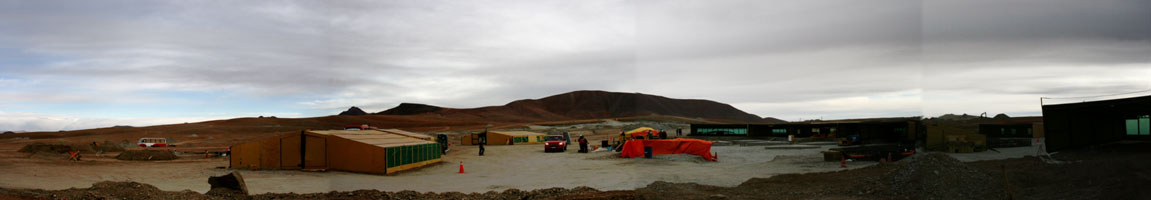
Figure 2: A panorama of construction at the Atacama Compact Array (ACA) site. Concrete poured for foundations must be cured at a controlled temperature inside tented structures (center). The ACA has 22 foundations and will be used for initial astronomical validation.
Meanwhile, acceptance tests will be completed for a second antenna, produced by VertexRSI under contract with Associated Universities Inc. It will be equipped with the Front End recently delivered from the East Asian Front End Integration Center in Taiwan, and it will follow a similar set of testing procedures.
The remaining three Melco and eight Vertex antennas on the site will follow. Parts for the first antenna produced by AEM under contract with ESO have also arrived at the OSF and these antennas will join the growing antenna family during the year.
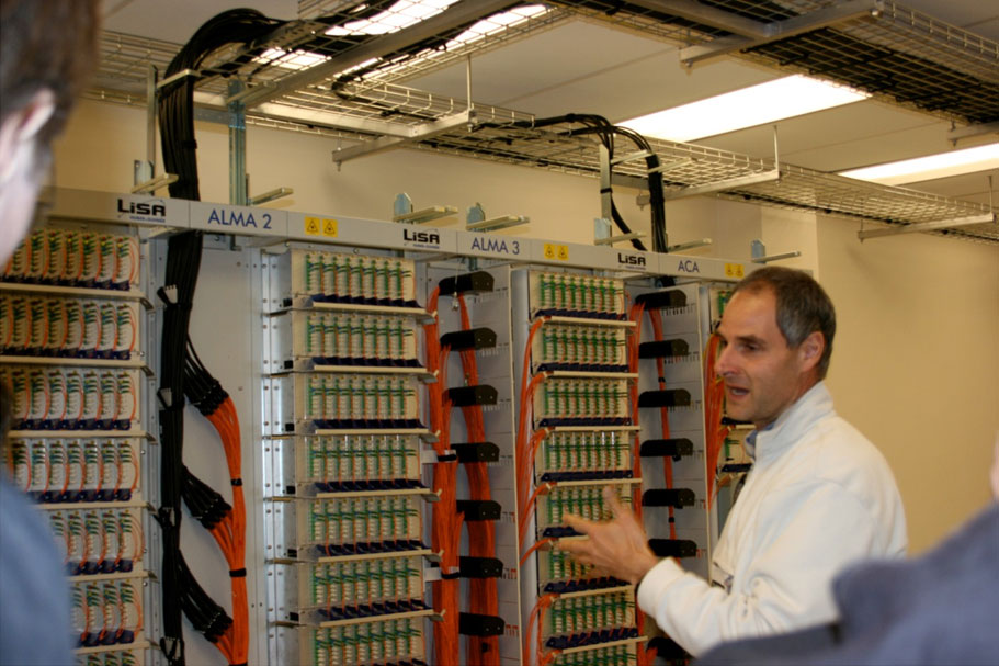
Figure 3: Backend lead Fabio Biancat Marchet shows the newly completed fiber optic patch panel in the AOS Technical Building to members of the AAER panel.
At the AOS antenna foundation construction continues. The first 12m antennas will occupy foundations within the Atacama Compact Array (ACA) area, for which the power and fiber optic cable infrastructure construction are more straightforward than in the larger Compact Array cluster. Fiber optics bring the antenna signals to the correlator at the AOS Technical Building where the fiber optic patch panel was recently completed. These steps lead to astronomical validation of the fledgling ALMA array expected later this year.
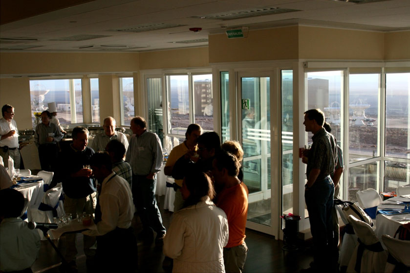
Figure 4: Members of the AAER Committee enjoyed dinner in the newly completed OSF Technical Building, including a panoramic view of the antennas: Vertex (right) and Melco (left) antennas.
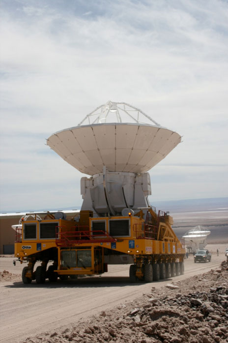
Figure 5: ALMA transporter Otto moves Melco antenna No 4 from the contractor area to the OSF Technical Building area. Vertex Antennas No 2 and No 1 are also visible (background right). This was the first move of an antenna by Otto, and the first move of a Melco antenna; the test before the AAER Committee went flawlessly.
Annual ALMA External Review
A Review of the ALMA Project was held 9-11 December 2008 in San Pedro de Atacama, Chile with visits by the panel to the OSF and AOS sites. The Review was commissioned by the ALMA Board to inform the Board and funding agencies as to the status of the Project, including management, progress, schedule, budget performance, current issues and risks for ALMA construction and operations. At the review, members of the Joint ALMA Observatory, Integrated Project Team (IPT) leads, and other key personnel outlined the progress since the last Review, with emphasis on items of concern at that Review. Many of the accomplishments described above were highlighted. Additional accomplishments included strengthening of the management structure and the establishment of schedule control mechanisms as production lines ramp up.
Science
ALMA’s increase of two orders of magnitude in sensitivity and resolution, coupled with its prowess at imaging on all spatial scales, promises transformational science. Figure 6 is an image of the Vega debris disk as observed with the IRAM interferometer by Wilner et al (2002). From this image, and images made with the VLA and JCMT, Wyatt constructed a model of the disk structure. Using this model with the CASA simulator almasimmos, along with specifications for thermal and atmospheric noise, Reid constructed the simulated ALMA observation on the right.
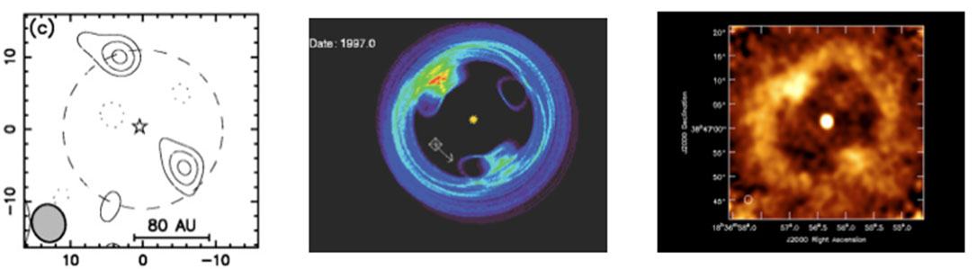
Figure 6: Three views of the Vega debris disk. Left: IRAM image (Wilner 2002). Center: Wyatt model (2003). Right: Simulation of Wyatt model as observed by ALMA (Reid 2008).
Many of the structures hypothesized by Wyatt should be observed by ALMA. Most exciting among these perhaps is the rotation of the debris disk, observed as a migration of the material accumulated at points in the disk in resonance with an unseen planet, denoted by a cross in the Wyatt model. Note that Vega itself appears. As it is relatively bright and unresolved, it offers the possibility of self calibration of the image though that was not simulated in this instance. Vega is near the northern limit of ALMA imaging at a declination of 38 degrees.
Call for Proposals for NRAO Telescopes
J.M. Wrobel and R.C. Bignell
The NRAO announces the Call for Proposals for trimester 09B. The call is open now and will close on February 2, 2009 at 17:00 EST.
- Details of the call for the Green Bank Telescope (GBT) for observing from June 1, 2009 through September 30, 2009
- Details of the call for the Very Large Array (VLA) and the Very Long Baseline Array (VLBA)
- Observing periods and VLA configurations
Nominations Invited for the 2009 Jansky Lectureship
Dale Frail
The National Radio Astronomy Observatory invites nominations for the 2009 Jansky Lectureship.
The Karl G. Jansky Lectureship is an honor established by the trustees of Associated Universities, Inc. to recognize outstanding contributions to the advancement of radio astronomy. First awarded in 1966, it is named in honor of Karl G. Jansky who, in 1932, first detected radio waves from a cosmic source.
Please send your nomination, including a concise justification for your choice, to borahood@nrao.edu or to the Office of Science and Academic Affairs, National Radio Astronomy Observatory, 520 Edgemont Road, Charlottesville, VA, 22903-2475, by Monday, 16 February 2009.
Lab Notebook:
A Digital Back End for the VLBA
Sensitivity Upgrade Project
Mike Revnell, George Peck, Jon Romney, Craig Walker

The VLBA, completed in 1993, is now undergoing a development project to increase the sensitivity of the instrument. Until now, the VLBA has been able to observe only at a total sustained bit rate of 128 Mbps (32 MHz with 2 bit samples) with a maximum bit rate of 512 Mbps for special projects. However, the analog IF electronics provide over 500 MHz in each polarization from most of the receivers. This is enough bandwidth to support 4096 Mbps recording. New technology now will enable the VLBA to routinely observe at 4096 Mbps, fully utilizing the two existing IF signals from each receiver. There will be a 4 IF capability for dual band observing, although still subject to a maximum of 4096 Mbps.
The upgrade project will:
- increase the VLBA bandwidth to 512 MHz (2048 Mbps) per IF;
- increase maximum record rate by a factor of 8 to 4096 Mbps;
- increase sensitivity by a factor of 5.7 (X-band, 8 hr synthesis, ~ 10 µJy/beam).
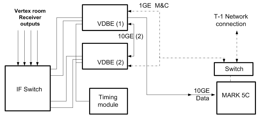
The existing VLBA electronics that will be replaced in the upgrade are the IF Distributors, the Baseband Converters, the Samplers, and the Formatter. The existing Mark5A recording system will be upgraded to a Mark5C system.
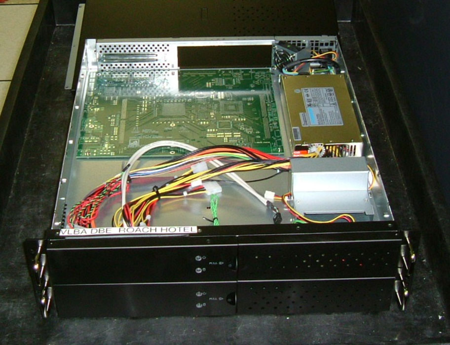
The upgraded system will include two VDBE (VLBA Digital Back End) modules, a timing module, and switches to route the signals in and out of the VDBE modules. The VDBE essentially re-implements the current VLBA backend system digitally. The heart of the VDBE is the ROACH (Reconfigurable Open Architecture Computing Hardware) board. The VLBA project will use two ROACH boards, along with dual 8-bit 1 G Sample/sec Analog to Digital Converter boards, to sample, filter, and format the data. The Mark5C uses large capacity commodity disk drives for recording. The input to the Mark5C from the ROACH is 10 G Bit Ethernet.
The ROACH board is the result of collaboration between NRAO, CASPER (Center for Astronomy Signal Processing and Electronics Research) at UC-Berkeley, and the South African KAT (Karoo Array Telescope) project group. The mission of the CASPER group is to provide easy to use, off-the-shelf hardware with development environments that enable non-experts to develop useful instruments. The South Africa group is using the ROACH as a major component of the MeerKAT project. CASPER provided the coordination of the development work on the ROACH and purchased the first ten boards. They are also porting their FPGA (Field Programmable Gate Array) development tools to the ROACH. The schematic design of the ROACH was done by the South Africa group, and the layout of the board was done by NRAO Socorro.
The ROACH utilizes the large bandwidth and high performance computing facilities of the Virtex 5 FPGA, the latest family of Xilinx FPGAs. The main components of the ROACH are the Virtex 5 FPGA, a Power PC CPU with associated memories, and I/O connectors.
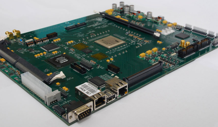
The ROACH is physically designed to fit into a standard ATX computer case and operate from standard supply voltages provided by PC power supplies. This minimizes the amount of work necessary to get one of the instruments running.
The Virtex 5 on the ROACH has a large amount of logic and signal processing hardware available. The chip selected for the ROACH has 640 18 x 18 bit hardware multipliers with associated accumulators, as well as 80,000 logic elements. Each logic element consists of a 6-bit lookup table that can implement any arbitrary Boolean function of 6 inputs with an associated storage element. This element can be configured as a flip-flop or latch. A significant number of 4 K bit block memories are available. This chip is suitable for processing the 8-bit samples that arrive at the ROACH board at the rate of 1024 M Samples/sec.
Haystack Observatory is providing a significant software contribution. Functions are implemented within the FPGA to process the very large amount of data entering the ROACH board from the Analog to Digital Converter Board. A polyphase subband filter bank splits the input bandwidth into four 128 MHz subbands, as the FPGA will be clocked internally at 256 MHz. There will be digital Local Oscillators and mixers as well as digital baseband filters to implement the functions that replace the VLBA baseband converters. Digital Re-quantizers will re-sample the filter outputs to 2-bits for recording, formatting, and packetizing logic. Ethernet packets will be built in order to send the data to the Mark5C recording system. Pulsecal tone detectors and switched power meters will also be implemented in the FPGA to collect monitor and diagnostic data. There will be polyphase modes for continuum observations, and digital down converter modes with flexible tuning for spectral line observations.
A major advantage of the ROACH board is that upgrades can be made without a change to the hardware. As requirements evolve, the ROACH functionality can be changed by re-programming the ROACH.
Spectrum Use after the U.S. DTV Transition
Harvey Liszt
Some time after February 17 2009 -- see the coda at bottom regarding the newly implemented "analog searchlight" program -- all full-power TV broadcasting in the U.S. will be digital (DTV). Full-power analog TV broadcasting will cease although some low-power analog broadcasting will persist. This change and the associated reallocation of the spectrum below 806 MHz will affect astronomical observing, not all for the worse, at least initially.
I. Above 698 MHz
The upper limit of full-power DTV broadcasting will be 698 MHz, channel 51. The spectrum between 698 and 806 MHz presently occupied by TV channels 52-69 will be reallocated to applications such as wireless broadband internet services, cellular telephone services, and a nationwide public safety broadband network. In the very near future, the spectrum band between 698 and 806 MHz will be largely empty as the winners of recent spectrum auctions begin to roll out their service. In the more distant future, the 698-806 MHz band will be used at a level and in ways comparable to the present cell phone bands, i.e., much more heavily and more ubiquitously than was previously the case for analog TV broadcasting.
The temporary absence of signals in the 698-806 MHz band presents a gradually-closing window of opportunity for radio observing. Also, the FCC has not yet designed a working model for the bands at 758-763 and 788-793 MHz which will eventually be dedicated to the national broadband network for emergency workers (the so-called Block D). This may be one of the last bands to fill in but it will probably impinge on radio astronomy use everywhere, eventually, including within the Quiet Zone.
II. Below 698 MHz
Channels 2-51 will continue to be occupied by TV broadcasting, in the same 6 MHz wide channels as before, and these 50 stations will have to accommodate the industry which previously occupied channels 2-69. A DTV signal fills its allocated band uniformly, as opposed to analog signals that are borne by narrower carriers within their band. The mean level of a DTV signal is generally somewhat below the peak level of an analog TV carrier. A convincing comparison of spurious emission levels beyond the allocated band edges remains to be demonstrated.
For a given market and channel, DTV signals generally use slightly lower power to achieve the same service level but the actual situation will be determined by which channels are occupied. A station whose signal moves from a lower-numbered analog channel to a higher-numbered digital channel may use higher power, roughly corresponding to the lower effective collecting area of isotropic antennas at higher frequencies.
Overall occupation of the spectrum below 698 MHz should decline on 17 February 2009 because stations are already broadcasting their DTV signal and many are broadcasting their old analog signal as well, which will go dark. This represents a reversal of the gradual infill of the TV bands which has occurred as DTV began to proliferate and stations replicated their analog broadcasts. Did radio astronomy notice as the TV bands filled up? Well, the situation is reversing itself somewhat.
III: Infill uses by so-called TV Band or white space devices
The FCC has also decided to allow local unlicensed non-broadcast-TV uses of DTV bands whenever a DTV channel is locally unavailable. Unused spectrum is generally known as "white space" and apparatus for utilizing the white spaces is known as white space devices or (at the FCC in the present context) TV Band devices. The FCC intent is to recreate the 2.4 GHz ISM bands used for WiFi etc., but throughout the lower-frequency DTV bands where signals propagate more easily. There are some additional details concerning which devices may use which channels, depending on whether the devices are fixed or mobile.
The FCC has issued rules which forbid the operation of TV Band devices within 2.4 km of existing radio telescopes, or in the protected band at 608-614 MHz (TV channel 37 shared with wireless medical telemetry) but without clarifying what it means to be within 2.4 km of, say, the Very Large Array, which is characterized in FCC documents by a point. The origin of the 2.4 km separation distance is obscure.
TV band devices will initially determine local spectrum availability using GPS and internet access to a database of DTV channel service contours; both capabilities will be needed before a TV Band device may broadcast. However, the FCC also intends eventually to license devices that merely sample the spectrum to determine availability. How such devices would know they are in the vicinity of a radio telescope is undefined.
The expected result here is that the spectrum below 698 MHz will be somewhat emptier of broadcast TV stations for quite some time, but will gradually fill in as use by unlicensed TV Band devices proliferates.
IV: Coda
At the behest of Congress, the FCC will allow full-power analog TV stations to remain on the air for at least 30 days after the scheduled 17 February 2009 DTV transition. Stations whose analog signals will not interfere with DTV broadcasts are being encouraged to remain on the air broadcasting public service information to assist whatever remnant of the TV-viewing public is surprised by the DTV transition and would lose access to the public safety information provided by watching TV. This program is known as the "analog searchlight" and it implements the recent "Short-term Analog Flash and Emergency Readiness Act."
Career Opportunities
Software Engineer (KFPA): The K-band Focal Plane Array Project at the Robert C. Byrd Green Bank Telescope (GBT) is seeking a Software Engineer to develop monitor and control software. The seven beam array under development will improve mapping speed and map calibration for extended molecular regions. Upon completion and commissioning of the seven beam array, work will commence on a larger array and complementary hardware infrastructure.
Software Engineer: The Software Development Division at the Robert C. Byrd Green Bank Telescope (GBT) is seeking a Software Engineer to join an exciting and diverse team, with responsibilities including continuing maintenance and enhancements of the current code base and future instrumentation development, e.g. the next generation of bolometer arrays for the GBT.
Deputy Assistant Director, Green Bank Operations (Scientist/A): The National Radio Astronomy Observatory is beginning a program to develop focal plane arrays for the Green Bank Telescope. We are looking for an energetic individual to be the deputy to the Green Bank site director and to provide scientific leadership for the focal plane array development program, particularly for the GBT’s high frequency range.
CASA Group Supervisor: The CASA Computing Division of the National Radio Astronomy Observatory is seeking a group supervisor to lead the CASA (Common Astronomy Software Applications) software group. The person filling this position will be directly involved in high-level design decisions for CASA, and will participate actively in the implementation of the resultant designs.
System Engineers: ALMA is seeking two System Engineers to join the team in Chile in support of the construction, commissioning and operational phases of the project. The positions involve duties in ALMA partner regions, Europe, East Asia, and North America, in the form of frequent missions to contribute to the production and integration activities of the ALMA sub-systems.
Lead Systems Engineer: ALMA is seeking a senior System Engineer for the ALMA Project to provide leadership in the definition and execution of SE activities across the project, and to manage the team in Chile in support of the construction, commissioning and operational phases of the project. The position includes responsibilities in ALMA partner regions, Europe, East Asia, and North America, requiring frequent missions to coordinate SE activities related to the production, integration and test of ALMA sub-systems.
Head of GBT Science Operations: The National Radio Astronomy Observatory is looking for an energetic individual to be responsible for the smooth and effective operation of the Green Bank Telescope from a scientific perspective. The head of science operations will lead a small group of (matrixed-managed) scientists and engineers to ensure the scientific output of the GBT remains high.

The National Radio Astronomy Observatory is a facility of the National Science Foundation operated under cooperative agreement by Associated Universities, Inc.
Copyright © 2009 Associated Universities, Inc.