NRAO eNews
December 2008 • Vol. 1, Iss. 7
- Upcoming Events
- Summer Student Research Assistantships
- Student Observing Support
- Undergraduate Interns
- Visitors Program
- Career Opportunities
- Exploration of the Solar Corona
- Expanded Very Large Array Status
- WIDAR Correlator Testing
- ALMA Construction
- Taiwan Welcomed as New North American ALMA Partner
- Proposals and Scheduling
- VLBA 22 GHz Amplifier Upgrade Project
 Lab Notebook: Low-Loss Materials Critical to Radio Astronomy
- Past Issues
- Contact the Editor
- Subscribe
- More Information
NRAO eNews: December 2008 • Volume 1, Issue 7
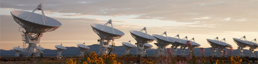
The NRAO Very Large Array near Socorro, New Mexico.
Upcoming Events
 The EVLA Vision: Galaxies through Cosmic Time
December 16-18, 2008
Socorro, NM
 NRAO Tenure Track Astronomer
Application Deadline is December 22, 2008
 National Radio Science Meeting
January 5-8, 2009
Boulder, CO
 AAS Meeting: NRAO Town Hall & Reception
January 7, 2009 | 5:30 – 7:00 p.m. PST
Long Beach, CA |
Hyatt Seaview Ballroom
 NRAO Summer Student Research Assistantships
Application Deadline is January 26, 2009
 NRAO Proposal Deadline (GBT, VLA, VLBA)
February 2, 2009 | 5:00 p.m. ET
 20th International Symposium on Space THz Technology
April 20-22, 2009
Charlottesville, VA
Summer Student Research Assistantships
Jeff Mangum, NRAO Student Programs Coordinator
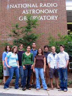
The Charlottesville Summer Students
Front Row L-R: Charli Sakari, Delia Mocanu, Evan Schneider, Daniel Lacasse
Back Row L-R: Jessica Coakley, Bryan Murphy, Tim Pennucci, Matt Schenker, Brian Sacash
Not in picture: Claudia Cyganowski, Allison Hammond, Anthony Hamzeh

The Green Bank Summer Students
L-R: Stephanie Moats, Anthony Woody, Marc Eimers, Colin Slater
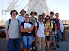
The Socorro Summer Students
Back Row L-R: Fred Davies, Josh Marvil, Ben Breslauer, Crystal Anderson, Alex Savello and Bobby Edmonds
Front Row L-R: Sarah Streb (Research Experiences for Teachers participant), Kiruthika Devaraj and Stephanie Capen
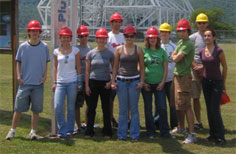
The 2008 NRAO Charlottesville Summer Students visit the Green Bank Telescope. L-R: Bryan Murphy, Allison Hammond, Brian Sacash, Evan Schneider, Tim Pennucci, Jessica Coakley, Charli Sakari, Daniel Lacasse, Matt Schenker, Anthony Hamzeh, and Delia Mocanu.
The 2008 NRAO Charlottesville and Green Bank Summer Students observing with the Green Bank Telescope. L-R: Colin Slater, NRAO Green Bank Summer Student Coordinator Toney Minter, Daniel Lacasse, Tim Pennucci, and Charli Sakari.
Now in its 50th year, the NRAO Summer Student Research Program seeks qualified applicants for its 2009 summer program. NRAO summer students conduct research under the supervision of an NRAO staff member at one of three NRAO sites (Socorro, New Mexico; Green Bank, West Virginia; Charlottesville, Virginia), on a project in the supervisor's area of expertise. The project may involve any aspect of astronomy, including original research, instrumentation, telescope design, astronomical site evaluation or astronomical software development. NRAO staff members choose their own student candidates from all applications received. The site to which a summer student is assigned depends on the location of the NRAO supervisor that chooses them. Students are encouraged to review the NRAO staff web pages to get an idea of the types of research being conducted at the NRAO. On their application, students may request to work with a specific staff member or to work on a specific scientific topic, or to work at a specific site.
The 2009 Summer Student Program will run for 10-12 weeks over the summer, from early June to mid-August. At the end of the summer, participants present their research results in a student seminar and submit a written report. Often, these projects result in publications in scientific journals. Financial support is available for students to present their summer research at a meeting of the American Astronomical Society, generally at the winter meeting following their appointment.
Besides their individual research projects, students take part in other activities, including a number of social events and excursions, as well as an extensive summer lecture series which covers aspects of radio astronomy and astronomical research. Students also collaborate on their own observational projects using the VLA, VLBA and/or GBT.
Visit our Summer Student Assistantships web page for further information about the NRAO Summer Student Research Assistantship program, including links to its on-line application.
Student Observing Support
Dale Frail
The NRAO Student Observing Support (SOS) Committee met in April and August 2008 to discuss the proposals that were submitted during the previous trimesters. The SOS committee, composed of five faculty members from U.S. universities, discussed the science case and student support application for each proposal. You will see below those that were selected to receive funding. Complete information on the Student Observing Support program is available on the NRAO web site.
- Loren Anderson (Boston U., Supervisor: T. Bania) was awarded $12,820 for work related to the GBT proposal 08C-007 “How Many HII Regions are in the Milky Way?”
- Fonda Day (U. New Mexico, Supervisor: Y. Pihlstrom) will receive $32,200 for work related to the VLBA proposal BP150 “Parallax and OH and H2O studies of Water Fountain PPNe.”
- Julia Deneva (Cornell, Supervisor: J. Cordes) will receive $13,000 for work related to the GBT proposal 08B-017 “Uncovering the Galactic Center Pulsar Population: Spectrum Estimation and Timing of Two New Pulsars.”
- Jackie Hodges (UC, Berkeley, Supervisor: R. Becker) was awarded $35,000 for work related to the VLA Large proposal AR685 “Deep VLA Observations of SDSS Stripe 82.”
- Ryan Lynch (U. Virginia, Supervisor: S. Ransom) was awarded $27,400 for work related to the GBT proposal 08C-076 “Long Term Timing of 55 Recycled Pulsars in Bulge Globular Clusters.”
- Steve Warren (U. Minnesota, Supervisor: E. Skillman) will receive $29,000 for work related to the VLA Large Proposal AO215 “VLA and HST: Star Formation History and ISM Feedback in Nearby Galaxies.”
- Kyle Willet (U. Colorado, Supervisor: J. Darling) will receive $35,000 for work related to the GBT proposal 08B-035 “A High Redshift OH Megamaser Survey.”
- Stephanie Zonak (U. Maryland, Supervisor: A. Harris) was awarded $18,000 for work related to the GBT proposal 08C-070 “Deep Zpectrometer Integration toward the Cloverleaf Galaxy.”
Undergraduate Interns
Dale Frail
The NRAO recently created the Undergraduate Student Internship Program. This program is intended for students enrolled in an undergraduate program at a U.S. university who are interested in pursuing research in radio astronomy, instrumentation development for radio astronomy, or areas of electrical engineering or computer science that are closely related to radio astronomy observing techniques or data analysis. Each NRAO undergraduate student intern will work part-time, usually during the academic year, under the supervision of an NRAO staff member at the Socorro, New Mexico; Green Bank, West Virginia; or Charlottesville, Virginia, site. Interested undergraduate students may contact Billie Orahood at borahood@nrao.edu. Further information will be available soon on the student web page.
Visitors Program
Dale Frail
The Office of Science and Academic Affairs (OSAA) oversees the NRAO Visitors Program. The program provides Ph.D. scientists and engineers in radio astronomy and related fields the opportunity to visit any of our sites at times other than while observing in order to interact with NRAO staff and carry out research programs, e.g., during sabbatical or summer leave from their home institutes. Information on this program can be found on the NRAO website.
During the period January to December 2008, the Observatory has welcomed the following scientists to our program:
- Jose Afonso (Lisbon) visited Socorro to work with Nissim Kanekar on a project to obtain a deep 325-MHz image of the Chandra Deep Field (South).
- Shuvra Battacharyya and Andrew Harris (University of Maryland) were awarded appointments at Green Bank to work with John Ford on digital processing for radio spectroscopy.
- Gabriella De Lucia (Max Planck Institute for Astrophysics ) visited Socorro to work with Veronica Strazzullo and Maurilio Pannella this month on the comparison of her models of galaxy evolution including AGN feedback with our observations, especially for the work on the deep VLA survey in the SWIRE Lockman Hole field.
- Malcolm Gray (University of Manchester, U.K.) spent his sabbatical in Socorro working on theory and computational models associated with astrophysical masers.
- Amanda Kepley (University of Virginia) works in Charlottesville with Kelsey Johnson on leading observational efforts at radio and millimeter wavelengths to study extragalactic star formation.
- Dongliang Liu (National Astronomical Observatory of China) visited NRAO in Charlottesville and Green Bank to work with Scott Ransom to learn about pulsar data processing.
- Duncan Lorimer and Maura McLaughlin (West Virginia University) came to Green Bank to work on follow-up observations of rotating radio transients and new pulsars discovered in the 350-MHz drift-scan survey with the GBT.
- Glen Morrison (CFHT) visited Socorro to work with Frazer Owen on the multi-frequency follow-up to the SWIRE deep radio survey and on the deep Abell 851 and GOOS-N radio surveys.
- Stacey Palen (Weber State University) worked with Gustaaf van Moorsel on EVLA/CASA user documentation and a software audit.
- Patrick Palmer (University of Chicago) visited Socorro to work with Miller Goss on parallax and proper motion studies of excited state OH masers in DR21.
- Vernesa Smolcic (California Institute of Technology) visited Socorro to work with Chris Carilli on VLA data.
Career Opportunities
The National Radio Astronomy Observatory (NRAO) has an opening for a tenure track astronomer position. The highest priority of the Observatory is to recruit new scientific staff that will enhance the scientific use and development of our new flagship facilities ALMA and EVLA. This year's search will focus on the scientific areas of astro-chemistry, proto-planetary disks, exo-planets, large-scale structure and time-domain astronomy, with technical expertise in millimeter and sub-millimeter spectroscopy, interferometric data analysis (including pipelines, data mining, high performance computing and algorithms). Preference will be given to applicants in these areas, although exceptional candidates with expertise in other areas will also be considered.
The NRAO currently operates the Very Long Baseline Array (VLBA), the 100-m Robert C. Byrd Green Bank Telescope (GBT), and the Very Large Array. It is also the North American lead in the construction of the Atacama Large Millimeter/submillimeter Array (ALMA), and is building the Expanded Very Large Array (EVLA). The completion of the EVLA and ALMA early in the next decade represents a one to two order of magnitude improvement in observational capabilities at centimeter through submillimeter wavelengths. Both facilities will be revolutionary in addressing a broad range of fundamental problems in astrophysics. Looking farther beyond, NRAO is increasingly involved in the planning of the next generation cm/m-wave facilities in the Square Kilometer Array (SKA) program.
The NRAO web site provides a description of the application process and other relevant details.
The deadline for applications and letters of recommendation is Monday, December 22, 2008.
The NRAO is an Equal Employment Opportunity Employer - women and minorities are encouraged to apply.
ALMA Postdoctoral Fellow: The North Radio Astronomy Observatory has an opening for a Postdoctoral Fellow to assist the ALMA Commissioning Team planning and executing the scientific commissioning of ALMA. As a member of the commissioning team, the successful applicant will work on preparing specific test procedures and trouble-shooting them, carrying out measurements, processing data and producing reports.
Software Engineer (KFPA): The K-band Focal Plane Array Project at the Robert C. Byrd Green Bank Telescope (GBT) is seeking a Software Engineer to develop monitor and control software. The seven beam array under development will improve mapping speed and map calibration for extended molecular regions. Upon completion and commissioning of the seven beam array, work will commence on a larger array and complementary hardware infrastructure.
Software Engineer: The Software Development Division at the Robert C. Byrd Green Bank Telescope (GBT) is seeking a Software Engineer to join an exciting and diverse team, with responsibilities including continuing maintenance and enhancements of the current code base and future instrumentation development, e.g. the next generation of bolometer arrays for the GBT.
Deputy Assistant Director, Green Bank Operations (Scientist/A): The National Radio Astronomy Observatory is beginning a program to develop focal plane arrays for the Green Bank Telescope. We are looking for an energetic individual to be the deputy to the Green Bank site director and to provide scientific leadership for the focal plane array development program, particularly for the GBT’s high frequency range.
Assistant Scientist (CASA Scientific Software Developer): The National Radio Astronomy Observatory (NRAO) invites applications for a software engineer, computer scientist, astronomer, or physicist with experience in astronomical data processing to develop software for the Common Astronomy Software Applications (CASA) package. The position is an NRAO Scientist position, with 25% of time available to pursue self-directed research.
Software Engineer: The National Radio Astronomy Observatory is seeking a skilled developer to participate in the development, maintenance and support to users of the ALMA Common Software (ACS) package. ACS is located between the ALMA application software and other basic commercial or shared software on top of the operating systems and provides a generalized common interface between applications and the hardware in order to facilitate the implementation and integration into the system of new software and hardware components.
CASA Group Supervisor: The CASA Computing Division of the National Radio Astronomy Observatory is seeking a group supervisor to lead the CASA (Common Astronomy Software Applications) software group. The person filling this position will be directly involved in high-level design decisions for CASA, and will participate actively in the implementation of the resultant designs.
System Engineers: ALMA is seeking two System Engineers to join the team in Chile in support of the construction, commissioning and operational phases of the project. The positions involve duties in ALMA partner regions, Europe, East Asia, and North America, in the form of frequent missions to contribute to the production and integration activities of the ALMA sub-systems.
Lead Systems Engineer: ALMA is seeking a senior System Engineer for the ALMA Project to provide leadership in the definition and execution of SE activities across the project, and to manage the team in Chile in support of the construction, commissioning and operational phases of the project. The position includes responsibilities in ALMA partner regions, Europe, East Asia, and North America, requiring frequent missions to coordinate SE activities related to the production, integration and test of ALMA sub-systems.
Head of GBT Science Operations: The National Radio Astronomy Observatory is looking for an energetic individual to be responsible for the smooth and effective operation of the Green Bank Telescope from a scientific perspective. The head of science operations will lead a small group of (matrixed-managed) scientists and engineers to ensure the scientific output of the GBT remains high.
NAASC Scientist - CASA Scientific Software Developer: The North American ALMA Science Center (the NAASC) has an opening for a scientist to work on the development of the new ALMA data reduction and analysis package CASA (Common Astronomy Software Applications).
NAASC Scientist - Commissioning Liaison: The North American ALMA Science Center (the NAASC) has an opening for a scientist to work, during commissioning and verification, as a liaison between the NAASC, which is headquartered at the NRAO headquarters in Charlottesville, VA and the ALMA telescope at its high site in northern Chile.
NAASC Postdoctoral Fellow - Splatalogue: The North American ALMA Science Center (NAASC) located at NRAO headquarters in Charlottesville, VA (on the campus of the University of Virginia) invites applications for a postdoctoral fellow to work with the NAASC scientific staff as it gears up to support the needs of the community when ALMA early science begins in 2011. This position is aimed primarily at independent research, but with an emphasis on exercising ALMA end-to-end software and databases from a scientific perspective.
NAASC Postdoctoral Fellow - CASA: The North American ALMA Science Center (NAASC) located at NRAO headquarters in Charlottesville, VA (on the campus of the University of Virginia) invites applications for a postdoctoral fellow to work with the NAASC scientific staff as it gears up to support the needs of the community when ALMA early science begins in 2011. This position is aimed primarily at independent research, but with an emphasis on exercising ALMA end-user software from a scientific perspective.
Exploration of the Solar Corona
Steven R. Spangler, University of Iowa
The solar corona is one of the most beautiful objects in astronomy, whether seen by the fortunate few in a total solar eclipse, or on the Internet with current spacecraft pictures. The corona is shaped into loops, streamers, and arcs. A physics student would correctly deduce that this structuring is due to the action of the coronal magnetic field.
The corona is also of major importance in contemporary astrophysics. It forms the base of the solar wind, and processes that occur there are probably repeated on a larger scale in the powerful winds of massive stars. The most intriguing feature of the corona is its high temperature, 1 – 2 million degrees Kelvin, versus 5800 degrees Kelvin for the solar photosphere. Although there have been many proposals for the mechanism or mechanisms responsible for this coronal heating, none of them is universally accepted.
Most theories for coronal heating invoke the coronal magnetic field. Testing these theories requires information on the large-scale field, which determines the overall shape of the corona, as well as on the small scale fluctuations which make up coronal turbulence.
The Very Large Array (VLA) has made a contribution to this effort to probe the nature of the coronal magnetic field. Since 1990, several University of Iowa students have worked with me on observing projects using Faraday rotation to probe the corona. Faraday rotation is a physical process in which the polarization angle of a polarized radio wave rotates as it propagates through an ionized gas (plasma) possessing a magnetic field. The angle of rotation depends on a number of factors, such as the density of the plasma and the strength of the magnetic field along the line-of-sight.
To make things challenging, the actual dependence is on the projection of the magnetic field on our line-of-sight. Thus, a strong magnetic field that is perpendicular to the line of sight has no effect, while a much weaker one parallel to the line of sight can produce a large, observable effect. Because our measurement is proportional to the product of the plasma density and the line of sight component of the magnetic field, we need independent information on the plasma density to obtain a measurement of the coronal magnetic field. Fortunately, the Sun is a well-observed object, and this independent information is available.
A cartoon representation of a coronal Faraday rotation measurement is shown in the figure below.
We choose observing times when a sufficiently bright radio source, usually a radio galaxy, is close to the Sun so its line-of-sight passes through the corona. We then measure its polarization position angle, and when possible, the position angles of several parts of the source.
Coronal observations have an appealing feature relative to similar sorts of observations of radio galaxies and quasars. We can separate the coronal contribution to the polarization position angle from other contributors, such as Faraday rotation in the interstellar medium. We simply observe the source when it is close to the Sun (see Figure 1), and then a few weeks later when the Sun is literally out of the picture. The difference in the polarization position angles is the Faraday rotation due to the plasma in the corona.
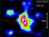
An example of a coronal Faraday rotation measurement is in Figure 2, taken from an article by Laura Ingleby and co-workers in the Astrophysical Journal.
Figure 2. A coronal Faraday rotation measurement (Ingleby et al. 2007, Astrophysical Journal 668, 520)
The left illustration shows a polarization image of the source through the corona. The contours are total intensity, and the line segments show the polarization position angles at different points on the source. This image was made at 1465 MHz on March 12, 2005, when the line of sight passed about 2.4 degrees from the Sun’s center. The illustration at right (Figure 2) was made ~ 2 months later, when the effect of the corona was absent. A rotation in the polarization position angles can be seen, corresponding to about 14 degrees. This is a fairly typical amount of Faraday rotation for this distance from the Sun.
Our observing projects have been conducted at 1465 MHz and 1665 MHz with the VLA in the A array or B array. We make the observations when a source is between elongations of about 1.3 and 3.2 degrees from the center of the Sun, or 5 to 12 solar radii. This conveys an idea of how deeply into the corona we can probe.
There are reasons for these limits. If a source is further from the Sun, the plasma density and magnetic field strength in the corona are too low to produce an easily measurable rotation. On the other hand, for lines of sight closer than about 1.3 degrees, the Sun moves into the closer sidelobes of the VLA antennas and the system temperature soars, making the data worthless.
What have we learned from these observations? We find that the polarity of the coronal magnetic field is accurately estimated by the magnetic field in the photosphere. Near times of sunspot minimum, these estimates suggest that about half of the corona has a magnetic field of one polarity, while the other hemisphere has the opposite polarity. Separating these is the coronal neutral line. This model reproduces the sign of our Faraday rotation measurements reasonably well. However, the strength of the coronal field as we measure it is greater than that from a common method of extrapolating the photospheric field, called the “potential field source surface method”. The evidence for this stronger coronal magnetic field comes not only from our VLA observations, but also from Faraday rotation measurements of spacecraft transmitters, made by Michael Bird and colleagues at the University of Bonn (see Bird et al. 1987, Solar Physics 109, 91).
In addition to information on the global coronal magnetic field, we have obtained information on smaller plasma structures in the corona. As we measure the Faraday rotation during an eight or ten hour observing session, we almost always observe variations or fluctuations with time. We believe these are due to the line of sight to the radio source passing through loops and other structures like those seen in eclipse pictures of the corona. Finally, we can measure, or in some cases place limits to, the properties of turbulence in the corona.
Like all types of radioastronomical research, this field will benefit from the availability of the EVLA. The increased sensitivity of the EVLA will permit types of coronal Faraday rotation measurements that are not feasible now. There are two obvious projects to be undertaken in the near future. First, observations should be made at 5 GHz, so we can go closer to the Sun, and therefore probe deeper in the corona. A combination of theoretical and observation arguments indicate that many important thermodynamic processes occur inside the 5 solar radius limit of the 1465 MHz observations. The smaller beam at 5 GHz means the increase in system temperature should occur closer to the Sun, and allow us to make measurements in previously unexplored territory.
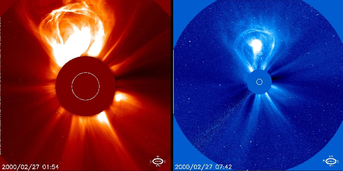
Second, it would be interesting to observe radio sources occulted by coronal mass ejections, or CMEs. Coronal mass ejections are big loops of plasma that explosively expand outward from the lower corona. A spacecraft-borne coronagraph picture of a CME is shown in Figure 3. The left-hand frame shows the CME at an earlier stage in its development, as imaged by the C2 coronagraph on the SOHO spacecraft. The right panel shows the same event at a later time, and the image comes from the wider field C3 coronagraph, also on SOHO. A Faraday rotation measurement through such a structure would be fascinating.
The physical processes that lead to CME liftoff are not understood. Measurements of the plasma state in their interiors, such as that provided by Faraday rotation, could help us better understand the basic physics of a CME and the way in which it evolves on its path through interplanetary space.
It is a tribute to the versatility of the VLA that an instrument originally intended for studies of radio galaxies, supernova remnants, etc three decades ago, can also provide interesting and nearly unique information on the corona of our Sun.
Expanded Very Large Array Status
M. M. McKinnon and the EVLA Project Team
Antennas continue to be converted to the EVLA design. A total of 18 antennas are now used for scientific observations. EVLA antennas accounted for 62.5% of all antenna hours used in scientific observations at the array in October 2008. The electronics outfitting of the 19th EVLA antenna is nearly complete, and the mechanical overhaul of the 20th antenna is well underway.
Good progress has been made in the production and installation of EVLA receivers. Four of the wideband, fully EVLA-compliant, C-band (4-8 GHz) receivers have been assembled, tested, and installed on antennas in the array. Six new Ka-band (26-40 GHz) receivers have been assembled, tested, and installed. The RF and mechanical designs of the new Ku-band (12-18 GHz) receiver are complete. The OMT, phase shifter, and square-to-rectangular waveguide transition were scaled from the design of the K-band receiver. Full production of the Ku-band receivers will start in late 2009.
The development of the wideband orthomode transducers (OMTs) for the EVLA receivers continues with encouraging results. Two samples of the final version of the L-band (1-2 GHz) OMT were manufactured and delivered to the NRAO. The design of all EVLA OMTs takes into account the straightforward assembly of each device, an important issue for their mass production. Tests showed that both OMTs easily comply with performance specifications without any tuning beyond the original assembly process. The L-band dewar kits were completed in late November, allowing the cold testing of the L-band OMTs to proceed. Cool down tests of the final version of the S-band (2-4 GHz) OMT showed that the receiver’s refrigerator has the necessary capacity to cool the OMT to the requisite temperature. The OMT is the largest source of thermal mass in the receiver. The RF testing of the entire S-band receiver is nearly complete. The fabrication and testing of a prototype, planar-style OMT for the X-band (8-12 GHz) receiver are underway in Green Bank. An X-band dewar was assembled in Socorro and sent to Green Bank for the tests. As a risk mitigation measure, an alternative, turnstile junction OMT for the X-band receiver is being designed at the Central Development Laboratory. The design of its three primary sections (turnstile junction, stepped impedance transformer, and combiner) is complete.
Production quantities of the 3-bit, 4 Gsps digitizer chips were delivered to the NRAO in September. The production of the sampler modules that contain the digitizers was delayed due to a clocking problem encountered with a serial-to-parallel converter on the sampler board. The production of the sampler modules is currently expected to resume in March 2009 at the rate of about one antenna per month.
A phase instability problem of unknown origin has existed in the EVLA local oscillator (LO) and intermediate frequency system for some time. The problem was recently found to reside in a crystal oscillator in the antenna reference generator module. A solution for the problem is currently under development. The problem was found using a new measurement technique that divides the antenna LO signals down to 512 MHz, transmits them back to the control building, and measures the signals with the recently completed round trip phase modules.
Six station boards for the WIDAR correlator are being tested at the DRAO in Penticton, British Columbia, in preparation for their deployment to the VLA site in early 2009. The station board provides delay tracking and digital filtering for the correlator. These boards, along with the four in the existing prototype correlator (PTC), will be used to assemble an intermediate 10-station correlator in the racks for the final correlator.
The first set of the "stage 3" baseline boards in the WIDAR correlator have been built. The baseline board contains the correlator chips where the correlations are computed. The functional testing of these boards is currently underway in Penticton.
Industry standard, quality control tests of the correlator chips were successfully completed. The tests indicate that the chip is very robust from a reliability standpoint. All of the production correlator chips have now undergone a burn-in, screen test at full speed. The failure rate of the chips was 0.7%, due largely to incomplete scan-test coverage, and partially due to infant mortality induced by the burn-in screen. This low failure rate means that the spare chips on hand will be more than sufficient for the lifetime of the correlator. The chips have been delivered to the manufacturer of the correlator circuit boards.
A critical design review (CDR) for the correlator was held in Socorro on December 2-3.The purpose of the CDR was to determine the production readiness of the major circuit boards in the correlator. The results from the on-the-sky (OTS) tests with the PTC figured prominently in the review. Preliminary indications from the review indicate that board production can proceed provided that a problem with power supplies on the station board is resolved and that the remaining laboratory tests of the stage 3 baseline boards are successfully completed. Given the positive outcome of the CDR, the full production of the correlator circuit boards will likely commence in early 2009.
Modifications to the Executor software of the EVLA monitor and control system allowed OTS tests with the PTC to be carried out using EVLA antennas simultaneously with ongoing VLA observations. The tests included the preparation of scripts that were executed using a test executor. Graphical user interfaces were developed and used to configure and monitor low-level board components. The actual testing required the painstaking debugging of a series of low-level problems in both hardware and software.The OTS tests are now carried out routinely.
OTS testing with the PTC has also included the production of meta-data that conform to the Science Data Model (SDM), as well as binary data that conform to the binary data format (BDF) specified in the SDM. The data from the OTS tests have been loaded into CASA and AIPS for analysis. An ongoing effort to improve this process is underway. Changes to the Executor, correlator backend, and meta-data and capture modules allow SDMs to be produced without hand-editing, making significant progress toward the goal of automating the process of merging SDMs and BDFs. The generation of the SDM/BDF combination enables one to load the data into CASA and AIPS on a routine basis.
Several features were implemented in the Observation Preparation Tool (OPT) to aid the Ka-band observations that will be made in the near future. Among these were the ability to specify scheduling constraints, such as wind velocity and atmospheric phase, the ability to perform Doppler tracking, a richer calibrator search mechanism, and summary listings of the scans that comprise a scheduling block. Support for tipping scans and fixed-date specification of scheduling blocks was also added. The OPT is now ready for the next phase of testing, which will expose the tool to a wider audience and will involve running the execution scripts produced from the information collected in the observation configuration process.
A review of the Virtual Correlator Interface (VCI) was held. The VCI is the protocol through which tools such as the OPT will communicate configuration requests to the WIDAR correlator. The document describing the VCI lists the details of all correlator configurations and operations in all observing modes. Software is being written to implement the VCI. Work began on a user interface for configuring WIDAR. The interface will be the first phase of WIDAR support within the OPT. It will be used in correlator testing in early 2009.
A National Science Foundation mini-review of the EVLA project was held on September 10, 2008. The review committee was impressed with the excellent progress made on the project. The committee commended the NRAO “… for carrying out the EVLA upgrades while continuing operations with the VLA system, resulting in important scientific results by the user community during the interim construction period.” The committee also noted that the scope of software development appeared to have expanded to facilitate access by the broader astronomical community and advised the project to ensure the critical software required for EVLA commissioning and initial science operations be completed first. Finally, the committee encouraged the project to share its plans for commissioning and operations with the community as soon as possible.
WIDAR Correlator Testing
M.P. Rupen and the EVLA Project Team
The WIDAR Prototype Correlator for the EVLA has been undergoing tests in New Mexico ahead of ordering the full production hardware. Since September 25 this prototype has had four Station Boards, enabling 4-antenna tests. The tests so far have focused on confirming that the correlator hardware has no major flaws, and the results have been impressive. The correlator has powerful spectral capabilities, and the typical mode we have been testing involves dumping 8192 channels covering 1 GHz (125 kHz/channel) every second for the 6 baselines; the data rate is then about 0.4 MB/s (1.4 GB/hr), about a factor of two greater than the VLA's peak of 200 kB/s. Both AIPS and CASA seem to handle this fine.
Key results so far include the following:
- Robust fringes in both D and A configuration for all bands from 1 to 45 GHz. A sample observation of 3C 84 covering 512 MHz is shown in Fig. 1, while Fig. 2 zooms in on the Orion water masers at 22 GHz.
- The observed phase and delay are consistent over many hours, when switching sources and/or observing frequencies and bands.
- The closure phase is stable over time (many hours at least), and both the closure phase and the rms noise integrate down as expected when averaging over frequency and time. Fig. 3 shows a self-calibrated image of the 4 Jy calibrator J0217+7349, achieving a peak:rms noise dynamic range of 72,800:1.
- Observations of a blank field for 2.3 hours at 8-9 GHz show no correlator artifacts to an rms noise level of 0.05 mJy/beam.
Our efforts with the current WIDAR Prototype Correlator over the next months will focus on cleaning up various software issues that we uncovered while checking out the hardware. This prototype will finally be turned off when the first boards for the final correlator arrive, currently scheduled for late spring 2009.
Figure 1. 3C 84 from 1.244 to 1.756 GHz, at 62.5 kHz resolution (one baseline).There are very strong interference signals from satellites from 1520 to 1630 MHz, which produce the faint lines in that regime; similarly the Albuquerque radar signals occupy IF 2, while (old-style) VLA polarizer suck-outs are clearly seen around 1460 MHz. The absorption lines in IF 3 are due to real HI absorption, from gas in the Milky Way (1420 MHz) and in the host galaxy (1380 MHz). The sharp cutoffs at the subband edges are due to the correlator's digital filters. Note the smooth phase connection within and between the subbands, even near strong radio frequency interference lines. The VLA could cover 6.25 MHz at this spectral resolution.
Figure 2: Zooming in on Orion's water masers. This observation used 64 MHz subbands with recirculation to obtain a spectral resolution of 31.25 kHz (0.4 km/s) over 512 MHz (7000 km/s). Here we show 400 channels, or 12.5 MHz — twice the bandwidth available to the current correlator at this spectral resolution, but only 2% of the total bandwidth covered by the EVLA's Prototype Correlator.
Figure 3: J0217+7349 observed with the WIDAR Prototype Correlator (4 antennas) at 4.588-5.612 GHz for 2.2 hours. The rms noise level is 0.057 mJy/beam, while the peak is 4.15 Jy.
ALMA Construction
Al Wootten
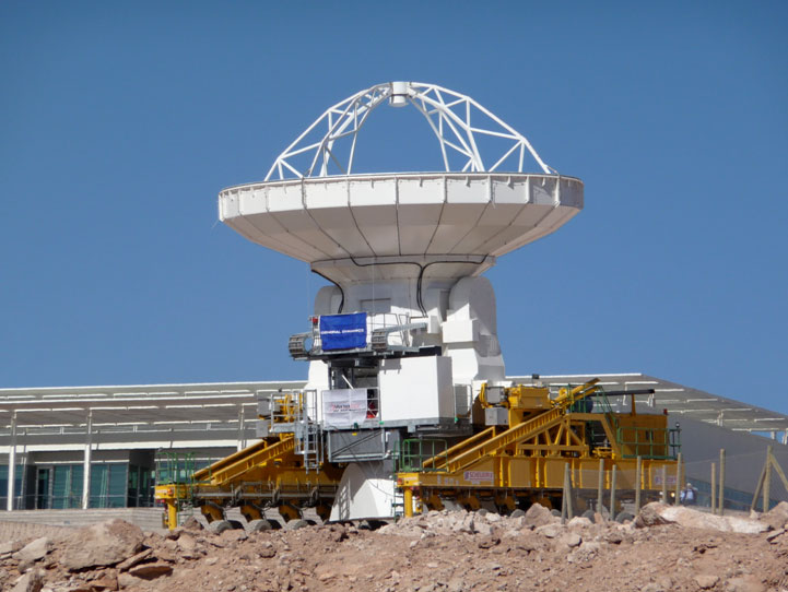
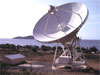
Figure 1. Antenna transporter Lore moves a Vertex antenna past the OSF Technical Buildings to a testing site.
Eight Vertex antennas and four Mitsubishi Electric Company (Melco) antennas are now at the Operations Support Facility (OSF) in Chile; major parts of the eighth Vertex antenna arrived on Thanksgiving Day. Tests continue on the antennas, with the first acceptance of an antenna, a Melco antenna, expected within days. Acceptance of the first Vertex antenna should follow shortly thereafter. On November 20, Lore, one of the two mammoth antenna transporters, moved an assembled Vertex antenna from the Site Erection Facility building to an antenna foundation above the Operations Support Facility to await testing.
The annual ALMA External Review will be held in early December. An external panel will examine ALMA’s progress during the preceding year and the project’s plans for the coming year.
ALMA personnel have moved into offices in the new OSF Technical Building complex, and its tele-conferencing facilities have been inaugurated.
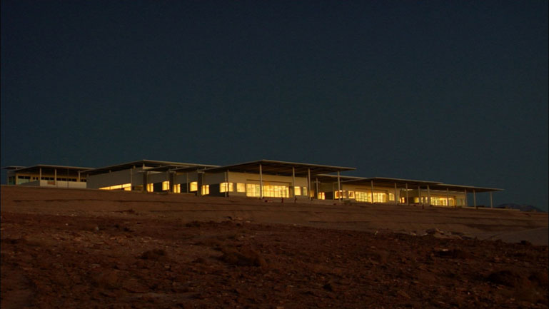
Figure 2. Work continues past sunset in the new OSF Technical Building, seen here just before drawing of the nightshades
Taiwan Welcomed as New North American ALMA Partner
John Stoke
NRAO has announced a formal agreement enabling Taiwanese astronomers to participate in the North American component of the international ALMA partnership, alongside American and Canadian astronomers. Taiwan's efforts will be led by the Academia Sinica Institute of Astronomy and Astrophysics (ASIAA).
The agreement, signed by the Taipei Economic and Cultural Representative Office and the American Institute in Taiwan, provides for approximately $20 million in ALMA construction funding through the National Science Council (NSC), Taiwan's equivalent to the U.S. National Science Foundation (NSF) and Canada's National Research Council (NRC), which have jointly funded North America's existing contribution to the international ALMA project.
Activities under the agreement will include joint research projects, development projects, collaboration on construction, support of observatory operations and other forms of cooperation. Access to ALMA observing time will be shared, as will membership on advisory committees.
"Taiwan is a world-class center for submillimeter-wavelength astronomical research, and we're delighted that the ALMA project and all its future users will benefit from the resources and expertise that Taiwan's deepening participation brings to this great, global endeavor," said Dr. Fred Lo, NRAO's director.
This new agreement increases and diversifies Taiwan's Academia Sinica investment in ALMA beyond the levels achieved through its participation in the East Asian component of the ALMA partnership, which is led by the National Astronomical Observatory of Japan. The agreement mirrors previous ones affording Taiwan astronomers enhanced access to NRAO's U.S.-based research facilities.
"ALMA will be one of the greatest ground-based observatories of the coming decade, and we look forward eagerly to working alongside our colleagues at the NRAO, and with the other ALMA partners, to make ALMA even more successful," said Dr. Paul Ho, ASIAA's director.
Proposals and Scheduling
VLA/VLBA Scheduling Officers schedsoc@nrao.edu
VLA/VLBA Proposals and Scheduling
The table shows the next two deadlines for regular and large proposals for the Very Large Array (VLA) and the Very Long Baseline Array (VLBA).
| Array | Deadline | Observing Period | Configuration |
| VLA | 2009 Feb 2 | 2009 May 18 - 2009 May 29 | Move |
| 2009 May 29 - 2009 Jun 15 | CnB | ||
| 2009 Jun 15 - 2009 Jun 19 | Move | ||
| 2009 Jun 19 - 2009 Sep 14 | C | ||
| 2009 Jun 1 | 2009 Sep 14 - 2009 Sep 25 | Move | |
| 2009 Sep 25 - 2009 Oct 12 | DnC | ||
| 2009 Oct 12 - 2009 Oct 16 | Move | ||
| 2009 Oct 16 - 2010 Jan 11 | D | ||
| VLBA | 2009 Feb 2 | 2009 mid May - 2010 mid Sep | |
| 2009 Jun 1 | 2009 mid Sep - 2010 mid Jan |
- VLA details
- VLBA details
- Proposal submission (use your "my.nrao" account or create one)
- Scheduling (dynamic and fixed date)
VLBI HSA Proposals and Scheduling
The NRAO handles regular proposals for the VLBI High Sensitivity Array (HSA) at the same deadlines as for the VLBA. The HSA includes the VLBA, VLA, GBT, and Arecibo in the U.S., plus Effelsberg in Germany.
- HSA details
- Proposal submission (use your "my.nrao" account or create one)
- Scheduling (fixed date)
Global cm VLBI Proposals and Scheduling
The NRAO and the European VLBI Network (EVN) jointly handle proposals for observing time on the Global VLBI Network at centimeter wavelengths. The deadline is 2009 Feb 1 for the session in 2009 May/Jun.
- VLBA details
- EVN details
- Proposal submission (use your "NorthStar" account or create one)
- Scheduling is on fixed dates during global sessions
Global 3mm VLBI Proposals and Scheduling
The NRAO and a set of European observatories jointly handle proposals for VLBI observing time at a wavelength of 3mm on the Global mm-VLBI Array (GMVA). The deadline is 2009 Feb 1 for the session in 2009 Oct.
- GMVA details
- Proposal preparation (via a LaTeX template)
- Proposal submisson is via e-mail to propsoc@nrao.edu and propvlbi@mpifr-bonn.mpg.de
- Scheduling is on fixed dates during global sessions
VLBA 22 GHz Amplifier Upgrade Project
Craig Walker
Efforts are under way to significantly improve the sensitivity of the VLBA. The major element of this effort is the bandwidth upgrade that has been reported elsewhere. But there are also opportunities for significant improvement in some of the receivers, especially at the higher frequencies. Some of the most important science being done on the VLBA involves observation of faint water masers in the 22 GHz band, one of the bands where current state-of-the-art amplifiers are much lower noise than the original VLBA amplifiers. Spectral line observations do not benefit from bandwidths wider than what is needed to see all lines in a source, so the best way to improve the capability of the VLBA for the maser observations is to improve the receivers. Of course, any receiver improvement also benefits continuum observations in the same band. Therefore, during 2007, the amplifiers in the existing VLBA 22 GHz receivers were replaced with the much appreciated financial help of the Max-Plank-Institut für Radioastronomie. The final report for the upgrade is in VLBA Sensitivity Upgrade Memo 21.
The low noise amplifiers in the VLBA 22 GHz receivers were replaced with Cryo-3 amplifiers from the NRAO Central Development Laboratory. Most other parts of the system, including feeds, polarizers, and dewars were retained to contain costs. The receiver temperatures were reduced by about a factor of about 2.4. Taking into account the contributions from spillover and the atmosphere, the sensitivity of the array was increased by a factor of 1.6. The reduction in system equivalent flux density (SEFD) by about 38% significantly exceeded the project goal of 30%. The improvement is equivalent to increasing the integration time, or the bandwidth for a continuum source, by a factor of 2.5. The new amplifiers also made the effect of the atmospheric water vapor line at 22 GHz obvious so a new standard observing frequency was established at 23.8 GHz, away from the peak of the line. For continuum observations in winter conditions, the sensitivity at that frequency is about 1.8 times greater than with the old system at 22.2 GHz. The expected benefit in wetter seasons should be even greater. The upgrade was completed in January 2008.
Figure: Improvement in on-sky performance of the 22 GHz upgraded system under good weather conditions. The first pair of bars for each station, one for each polarization, shows the SEFD before the upgrade. The second pair shows the SEFD after the upgrade, at 22.2 GHz. The third pair shows the SEFD after the upgrade at 23.8 GHz, off the center of water line. Note that station BR had recent model amplifiers before the upgrade which is why it did not see much improvement. The benefit of 23.8 GHz is especially apparent at SC, by far the wettest site at this time of year.
The attached figure shows the zenith SEFD measured using most of the pointing and gain observations taken between October 2006 and January 2007, before the upgrade, and between January and April, 2008, after the upgrade. The SEFD is a good measure of the overall sensitivity of an antenna taking into account the telescope gain, the receiver temperature, and the additional contributions to system temperature from sources outside the receiver such as spillover and the atmosphere. For reference, the SEFD of typical VLBA receivers between 1.4 and 8 GHz, where the both amplifiers and the atmosphere make only small contributions, is around 300 Jy. Because of the fitting methods used in the data analysis, the results presented correspond to the performance under the best conditions encountered during the period of the analysis. The average across sites of the zenith SEFD at 22.2 GHz before the upgrade was 796 Jy. After the upgrade, the average zenith SEFD was 502 Jy. Off the center of the atmospheric water line, the SEFD is even lower. At 23.8 GHz, in the standard frequency that has been added in the middle of the 23.6-24.0 GHz protected band, the SEFD in good conditions is 441 Jy. The sensitivity at 23.8 GHz is now a factor of 1.8 greater than the pre-upgrade sensitivity at 22.2 GHz, which should significantly benefit continuum projects. Note that, in wetter conditions, such as summer, the absolute sensitivity will be less because of added water vapor. But the difference between 22.2 and 23.8 GHz will be even higher than the winter numbers shown in the Figure indicate, making it even more beneficial to shift continuum projects to 23.8 GHz.
Lab Notebook:
Low-Loss Materials Critical to Radio Astronomy

The minimization of dissipative losses in radio astronomy receivers is a never-ending engineering task. Any resistive loss also adds noise to the system. Just 1% (0.04 dB) of loss in an RF component at room temperature at the input of a receiver will add 3 Kelvin of noise to the system temperature. With a typical system temperature of 20 K, this translates to 15% loss of sensitivity and a 32% increase in the required observing time. Small resistive losses also degrade the quality of frequency-selective filters needed to reject strong interfering signals that can overload the low-noise amplifier stages.
Cooling a lossy component not only reduces the noise it adds to the system in proportion to its physical temperature, it also reduces the resistive loss, even in normal metals, such as copper. In the October 2008 issue of the International Journal of Infrared and Millimeter Waves, Ricardo Finger and Tony Kerr describe their careful measurements of low-temperature RF losses in a variety of metals typically used in front-end receiver components. The bulk resistivity of very pure copper is well known to drop by several orders of magnitude at temperatures below about 30 K. A factor of 50 is typical for a good grade of commercially available copper. However, RF current flows only near the surface of a conductor so a 50X reduction in bulk resistivity produces only a 7X improvement in RF loss, and this requires a smooth surface on the scale of the RF “skin depth” (less than a micrometer).
To test whether the RF loss reduction at low temperatures is realized in practice and whether some metals and surface finishes are better than others, Finger and Kerr performed two experiments. The first was a DC measurement of a thin copper strip immersed in liquid helium to verify that its bulk resistivity dropped by the expected factor of 50. The second experiment consisted of a simple resonant microwave structure, shown in Figure 1, where the sharpness of its resonances, its “Q”, was inversely proportional to the RF loss in the metal conductor in the structure.
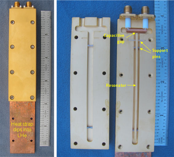
Figure 1. Microwave resonator used to measure RF loss in normal metal conductors at room temperature and at 4 Kelvin.
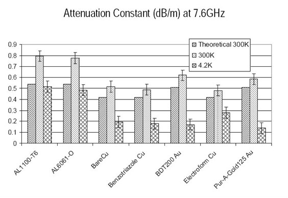
Some of the results of the resonator tests on various forms of aluminum, copper, and gold are shown in Figure 2. The ratios between warm and cold losses ranged from about 2 to 4 instead of the 7 expected for copper, and the better materials at room temperature were not the better materials when cold, which suggest that surface properties play an important role. Interestingly, a particular gold plating process, called “Pur-A-Gold125”, gave the best cold results and will be given serious consideration in future component manufacture.
The ultimate low-loss materials are the superconductors. These are used in mm-wave SIS mixers, which, as the ‘S’ in the name implies, must be superconducting to work at all. However, these superconductors require refrigeration to ~ 4 K. Most cm-wave receivers are cooled to only 15 K or higher. High-temperature superconductors (HTS) work at temperatures as high as 60 K or above, but their manufacture is complex and they have been economical for RF applications only in high volume, such as the cellular telephone industry. However, this has changed recently with the advent of a small number of firms that specialize in HTS circuit layout and manufacture.
In a collaboration with Michael Lancaster and Srikanta Pal at the University of Birmingham (UK), the NRAO recently took delivery of two band-stop filters made with HTS. These have an extremely sharp 50 dB notch at the frequency of the very strong Sirius and XM satellite signals at 2.33 GHz with very low attenuation below 2.31 and above 2.35 GHz as shown in Figure 3. These filters have been installed after the cooled LNAs in the GBT S-band receiver with excellent results for wideband pulsar observations as shown in Figure 4. The top portion of this frequency range was unusable before the filters were added because the satellite signals overloaded the correlator digitizer and the front-end itself when the telescope was pointed in the general direction of the satellites. Roger Norrod specified the requirements of the HTS filter and measured its final characteristics as reported in Electronics Division Technical Note 210.
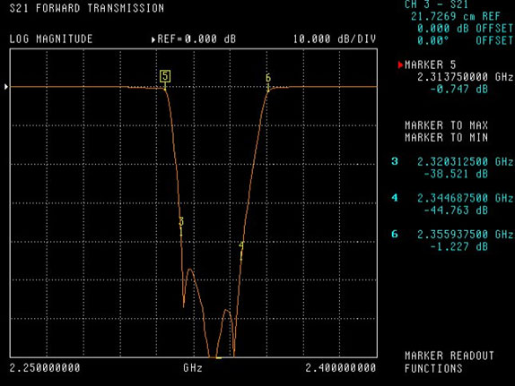
Figure 3. HTS notch filter attenuation as a function of frequency. The vertical scale is 10 dB per division. Note the frequencies to the right of the graph of the markers 3, 4, 5, and 6 on the curve.
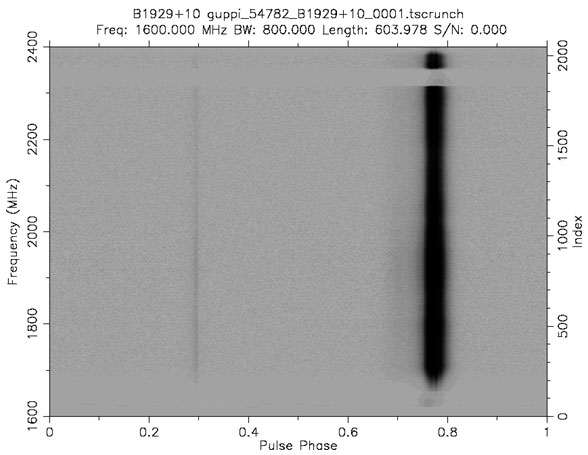
Figure 4. Dynamic pulsar spectrum of pulsar B1929+10 showing the sharp frequency band removed by the HTS notch filter near the top of the image.
The extremely low loss required for the sharp filter characteristics shown in Figure 3 is not achievable with normal metal conductors. However, HTS material cannot be used for all RF components because it is currently available for microwave applications as thin films deposited on a relatively high dielectric constant substrate. Also, the RF loss of HTS rises faster with frequency than it does for normal metals (as the square instead of the square root of frequency) so both types of conductors will have their advantages in different applications. Another place where HTS shows great promise for radio astronomy is in power splitter/combiners and hybrids in the transition from waveguide to microstrip at the input to the first cooled LNA stage. Mike Stennes has designed and is now testing a number of these components in an OMT design for the EVLA and as an input circuit for balanced HFET amplifiers. Stay tuned for more HTS developments.

The National Radio Astronomy Observatory is a facility of the National Science Foundation operated under cooperative agreement by Associated Universities, Inc.
Copyright © 2009 Associated Universities, Inc.