Doc Ewen: The Horn, HI, and Other Events in US Radio Astronomy
by Doc Ewen, © 2003
Slide presentation: Microwave and Millimeter Wave Applications in the 1970s and 1980s
In this slide presentation, I have selected three sensor developments during the 1970s and late 1980s that are characteristic of activities underway at that time: 1) The Buzzards Bay Bridge, Cape Cod Canal (BC)3; 2) The Eight Channel Co-boresighted Receiver System (ECCB); and 3) The Submillimeter Wave Astronomy Satellite (SWAS). (BC)3 and ECCB were important technical precursors needed to support the successful development of SWAS.
(Click on the thumbnails for larger photos and fuller explanations.)
Slide sections:
|
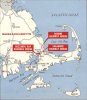
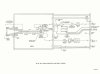
Slide 1: Map of lift bridge area at Cape Cod Canal.
|
| |
|
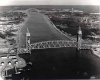
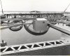
Slide 2: Aerial photo of Cape Cod Canal lift bridge and Bourne Bridge.
|
| |

|
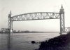
Slide 3: Lift bridge with the 544ft span in the "up" position.
|
| |
|
Slide 4: Lift bridge from rip rap, west side of bridge on Cape Cod side.
|
| |
|
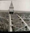
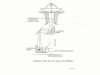
Slide 5: Tower on northwest side of Canal, taken from Cape Cod Tower.
|
| |
|
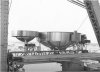
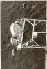
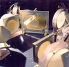
Slide 6: The four radiometer antennas looking toward zenith.
|
| |
|
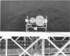
Slide 7: Close up look at the four parabolic antennas.
|
| |
|
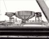
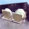
Slide 8: Close up look at the 740 and 1420 MHz parabolas with cylinder hoods.
|
| |
|
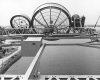
Slide 9: The antennas looking out over Buzzards Bay at 45° elevation angle.
|
| |
|
Slide 10: Antennas looking down at an angle near nadir.
|
| |
|
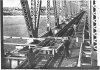
Slide 11: Antennas fully extended off bridge and looking just below the horizon.
|
| |
|
Slide 12: Antennas in stow position "on - bridge".
|
| |
|
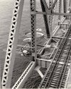
Slide 13: Antennas in stow position, photographed from the upper bridge structure.
|
| |
|
Slide 14: Antennas photographed from the top of the bridge.
|
| |
|
Slide 15: Antenna track during installation.
|
| |
|
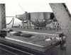
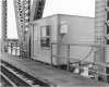
Slide 16: Enclosure for recording and control equipment, cantilevered off east side of bridge.
|
| |
|
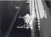
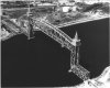
Slide 17: Aerial view of the bridge with the radiometric sensors in the operating mode.
|
| |
|
Slide 18: Introduction to Eight-Channel Co-boresighted Receiver System (ECCB).
|
| |
|
Slide 19: General description of the ECCB.
|
| |
|
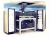
Slide 20: ECCB sensor system.
|
| |
|
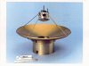
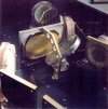
Slide 21: Cassegrain antenna with motor-driven subreflector.
|
| |
|
Slide 22: Sketch of Cassegrain antenna and signal path components at entrance to GOMUX.
|
| |
|
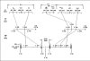
Slide 23: Sketch of signal paths in GOMUX from input to each of the eight receivers.
|
| |
|
Slide 24: Sketch of signal paths (with photo of GOMUX for reference).
|
| |

|
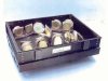
Slide 25: Close-up of components inside the GOMUX enclosure.
|
| |
|
Slide 26: Composite view of all quasi-optical components of the GOMUX.
|
| |
|
Slide 27: Close-up of components at the entrance to the GOMUX.
|
| |
|
Slide 28: Close-up of entrance componants from another direction.
|
| |
|
Slide 29: Components at the input to receivers 7 and 3.
|
| |
|
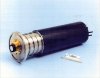
Slide 30: An ECCB receiver.
|
| |
|
Slide 31: 40-50 GHz cooled receiver functional diagram.
|
| |

|
Slide 32: Connector end of an ECCB receiver.
|
| |
|
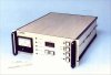
Slide 33: Front panel of the ECCB control unit.
|
| |
|
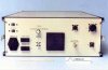
Slide 34: Back panel of the ECCB control unit.
|
| |

|
Slide 35: SWAS emblem.
|
| |
|
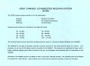
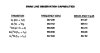
Slide 36: SWAS line observation capabilities.
|
| |
|
Slide 37: SWAS superheterodyne receiver scheme.
|
| |
|
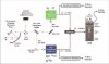
Slide 38: SWAS functional block diagram.
|
| |
|
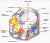
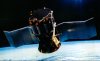
Slide 39: Integration of offset Cassegrain receiver with the cooling "cones".
|
| |
|
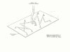
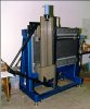
Slide 40: SWAS near field antenna range.
|
| |
|
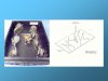
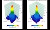
Slide 41: SWAS antenna patterns measured with the near field range.
|
| |
|
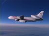
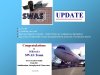
Slide 42: Launch aircraft flies north toward San Francisco with SWAS.
|
| |
|
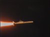
Slide 43: SWAS is "go" for orbit.
|
| |
|
Slide 44: SWAS in orbit in space (artist's conception, Ball Aerospace).
|
| |
|
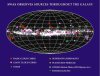
Slide 45: SWAS observes sources through the galaxy.
|
| |
|
Slide 46: Thank you to the SWAS team from John Youngblood, Militech CEO.
|
| |
|
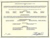
Slide 47: Congratulations from Smithsonian Astrophysical Observatory to the Militech team.
|
| |
Modified on Sunday, 27-Mar-2005 17:48:09 EST by Ellen Bouton
|

![[Doc Ewen looks into the horn antenna, 1950]](ewen_horn1s.jpg)
![[Doc Ewen and horn antenna, 2001]](ewen_horn2s.jpg)