NRAO eNews
October 2008 • Vol. 1, Iss. 5
- The Expansion of Supernova Remnant G21.5–0.9: Is PSR J1833–1034 the Youngest Pulsar?
- Discovery of a Small Group Driving the Evolution of an Edge-On Spiral Galaxy
- Cosmic Rays and the Magnetic Field in the Nearby Starburst Galaxy NGC 253
- Neutral Hydrogen Clouds in the M81/M82 Group
- ALMA Project Progress
- North American ALMA Science Center
- The ALMA Spectral Line Catalog
- The Birth and Feedback of Massive Stars, Within and Beyond the Galaxy: The NAASC Science Workshop for 2008
- Current Status
- VLA Configuration Schedule, Proposals, and Scheduling
- VLBA and HSA Proposals and Scheduling
- Global cm VLBI Proposals
- VLA and EVLA Spectral Line Observations Below 1200 MHz
- Status of Observing with the Transition Array
- VLBA Sensitivity Upgrade Project
- First 3mm Science Observations with the GBT and MUSTANG Call for Proposals
- The GBT Dynamic Scheduling System Update
- Progress on the Ka-Band Focal Plane Array for the GBT
- Opportunities for University-Led Technical Development Projects in Green Bank
- New NRAO Website Debuts
- The NRAO at the American Astronomical Society and American Association for the Advancement of Science Meetings
- Call for GBT Shared-Risk MUSTANG Proposals
- Large Proposals to Use NRAO Telescopes
- Chris Carilli Appointed Observatory Chief Scientist
- Eleventh Synthesis Imaging Workshop
- 2008 Grote Reber Medal Awarded to Sandy Weinreb
- NRAO Participates in the BEYA Conference
- NRAO Business Managers Meet in Chile
- NRAO Library News
- Past Issues
- Contact the Editor
- Subscribe
- More Information
NRAO Newsletter • April 2008 • Issue 115
Expanded Very Large Array (EVLA): Current StatusThe rate of antenna retrofits to the EVLA design is proceeding at the desired rate of about six antennas per year. A total of 14 EVLA antennas are now used in scientific observations and account for over 48 percent of all antenna hours used in observations. The retrofitting of the 15th EVLA antenna is underway. 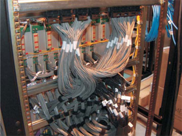
Figure 1. High speed data cables installed in a WIDAR station rack. Preparations are underway for the delivery of the prototype WIDAR correlator to the VLA site in mid-2008. Most components for correlator rack assembly are in place. The racks will be delivered to the VLA site in two shipments of eight racks each in the late spring and early summer of 2008. The assembly, labeling, and testing of the high-speed Meritec cables, which are used for interconnecting the correlator racks (Figure 1) were completed in Penticton, British Columbia. The 128 rack-to-rack cable bundles were delivered to the VLA site in March 2008. The beta prototypes of the correlator baseline board and station board were fabricated and delivered to Penticton in January 2008. Some problems were encountered with the fabrication of the baseline board, but no problems were found with station board fabrication. To reduce risk in the fabrication of baseline boards for the prototype correlator, quotations have been requested from two other suppliers, and more than one printed circuit board fabricator will build the boards. Board fabrication is on track for the delivery of the prototype correlator in mid-2008. Correlator chips are being produced by the chip manufacturer, iSine. The first set of 1,200 chips will be used for qualification testing and for the prototype correlator boards. The remaining 11,000 chips should be available in the summer, well in advance of final board production. A company that specializes in industry-standard integrated circuit qualification, failure analysis, and screen testing was selected to test the chips and evaluate production reliability. The two prototype quad-ridge sections of the S-Band (2–4 GHz) orthomode transducer (OMT) were delivered to Socorro. Laboratory tests of the OMT conducted in January 2008 show that the unit meets specification. The old VLA L-Band (1–2 GHz) dewar will be reused for the new S-Band receiver, and drawings are being made to document the required dewar modifications. The quad-ridge sections of the prototype C-Band (4–8 GHz) OMT are meeting specifications. Two issues remain to be resolved before the OMT can be placed in full production:
The prototype Ka-Band (26–40 GHz) receiver generally meets specifications and is currently undergoing tests of its local oscillator drive level. Preparations are being made for the mass production of the Ka-Band receivers this year. 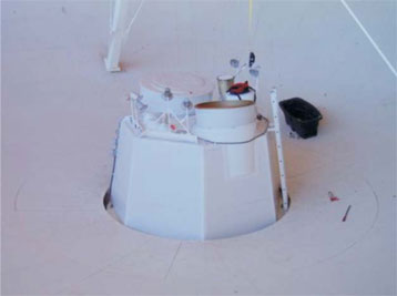
Figure 2. First S-Band feed horn installed in an EVLA antenna. Good progress continues on the production of feed horns for the EVLA receivers. The fiberglass lamination of 26 L-Band feed horns has been completed. All of the aluminum rings for the L-Band horns have been fabricated, and the fabrication of the rings for the S-Band horns continues. The purchase order for the centrifugal castings of components needed for the S-Band horn was placed, and the contract for the production lamination of the horn was issued in March 2008. The prototype S-Band horn was installed in an EVLA antenna (Figure 2). The machine shop in Green Bank built two prototypes of the Ku-Band (12–18 GHz) horn. Ten mounting towers for the Ku-Band feed horns have been completed. The redesigned L352 round trip phase module has been assembled and tested. The module now meets or exceeds all performance specifications. The project quantity of these modules will go into production after some minor modifications to the L352 printed circuit board and a final test in the array. A production order for the gain slope equalizers was placed, and partial deliveries of the equalizers have been received. The equalizers flatten the EVLA’s wide (2 GHz) bandpass prior to digitization and are located in the T304 downconverter module. The final versions of the P301/302 power supplies are now being refit into the antennas. They include full monitor, control, and safety features, as well as additional temperature sensors for the electronics racks and vertex room. These sensors have already enabled us to identify stability issues in the HVAC system and to correlate local oscillator stability issues with temperature changes. The remainder of these modules should be upgraded by mid-2008. The production of the M302 and M303 utility modules was started in December 2007. The modules provide a number of functions, including temperature sensors and emergency shutdown capabilities, to the vertex and pedestals rooms of the antennas. Considerable work has been devoted to the monitor and control (M&C) system for the WIDAR correlator. Delay and phase models for the station boards have now been implemented and tested. Support for the correlator module interface board has been added for the new baseline board phased array design. The graphical user interface for the correlator’s retiming, crossbar, and phasing boards was completed. A draft of a joint ALMA/EVLA correlator output Binary Data Format (BDF) specification document was completed. The BDF will allow the two interferometers to have a common data format, saving much effort on archive writing and reading software. A preliminary design has been made for the Meta-data Capture and Format (MCAF) subsystem. MCAF has been prototyped with focus on data collection, Science Data Model (SDM) handling, and communications. Transition observing continues to operate relatively smoothly under the EVLA M&C system. For example, the control and monitor processor has now run for well over 100 days without a crash, a significant improvement over the previous state. Recent significant improvements to the M&C system include the support of VLBA/VLBI observing, solutions of crosshand delays, cleaning up of many timing and data labeling issues, and an improved document tracking system for documents sent between the Executor and Interim Data Capture and Format. In addition, two new versions of the EVLA Operators Software were released, with improvements to the fringe and alert screens and a new screen for feed heater status. Instrument configuration capabilities were added to the Observation Preparation Tool (OPT). The OPT now has a model of the EVLA antenna electronics that can be used for baseband tuning. New ideas were developed for how the configuration of the WIDAR correlator will be presented to users of the OPT. The look and feel of the OPT was changed to be more like that of the Proposal Submission Tool. An initial design for archiving the visibility data from WIDAR, using a BDF and SDM that are consistent with that for ALMA, has been developed. The design will easily support the data rates from the prototype correlator. Work is being completed on the parminator, a webbased replacement for parmstool, which is an interface that operators will use to maintain many of the parameters essential to the operation of the EVLA. A document that gives a detailed description of the values in this database was written. The document was used to implement a system for rigorous error checking. M. M. McKinnon and the EVLA Project Team |

The National Radio Astronomy Observatory is a facility of the National Science Foundation operated under cooperative agreement by Associated Universities, Inc.
Copyright © 2009 Associated Universities, Inc.